|
|
|
PDF HV9123 Data sheet ( Hoja de datos )
| Número de pieza | HV9123 | |
| Descripción | High-Voltage Current-Mode PWM Controller | |
| Fabricantes | Microchip | |
| Logotipo | ||
Hay una vista previa y un enlace de descarga de HV9123 (archivo pdf) en la parte inferior de esta página. Total 18 Páginas | ||
|
No Preview Available !
HV9120/HV9123
High-Voltage, Current-Mode, PWM Controller
Features
• 10 to 450V input voltage range
• <1.3 mA supply current
• >1 MHz clock
• 49% maximum duty version
Applications
• Off-line high frequency power supplies
• Universal input power supplies
• High density power supplies
• Very high efficiency power supplies
• Extra wide load range power supplies
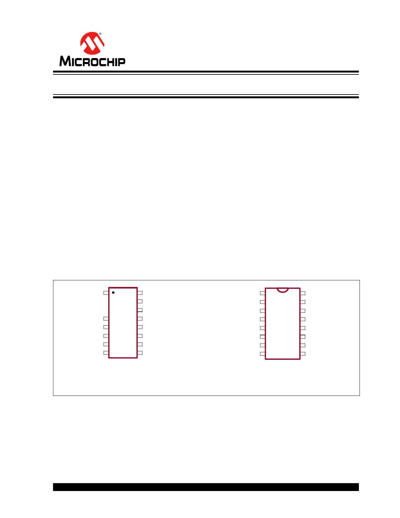
Package Types
1
16
Description
HV9120 and HV9123 are Switch-Mode Power Supply
(SMPS) controllers suitable for the control of a variety
of converter topologies, including flyback and forward
converter.
Using an internal, high-voltage regulator, HV9120 and
HV9123 can derive a bias supply for starting-up and
powering a converter from a variety of power sources,
such as a 12V battery or the rectified AC (230 VAC)
line.
HV9120/HV9123 controllers include all essentials for a
power-converter design, such as a bandgap reference,
an error amplifier, a ramp generator, a high-speed
PWM comparator, and a gate driver. A shutdown latch
provides on/off control. Device power consumption is
less than 6 mW when shutdown.
HV9120 offers 50% maximum duty and HV9123 offers
nearly 100% duty.
1 16
4
16-lead SOIC
See Table 3-1 for pin information
16-lead PDIP
2016 Microchip Technology Inc.
DS20005519A-page 1
1 page 
HV9120/HV9123
ELECTRICAL CHARACTERISTICS (CONTINUED)
Electrical Specifications: VDD = 10V, VIN = 48V, VDISC= 0V, RBIAS = 390 kΩ, ROSC = 330 kΩ, TA= 25°C, unless oth-
erwise noted.
Parameter
Symbol Min Typ Max Units Conditions
Error Amplifier
Feedback voltage
Input bias current
Input offset voltage
Open loop voltage gain
Unity gain bandwidth
VFB
IIN
VOS
AVOL
GB
Output source current
ISOURCE
Output sink current
ISINK
High-voltage Regulator and Start-up
Input voltage
Input leakage current
Regulator turn-off threshold
voltage
VIN
IIN
VTH
Undervoltage lockout
Supply
VLOCK
Supply current
Quiescent supply current
Nominal bias current
Operating range
Shutdown Logic
IDD
IQ
IBIAS
VDD
Shutdown delay
NSD pulse width
RST pulse width
Latching pulse width
Input low voltage
Input high voltage
Input current, input high voltage
Input current, input low voltage
Output
tSD
tSW
tRW
tLW
VIL
VIH
IIH
IIL
Output high voltage
VOH
Output low voltage
VOL
3.92 4.00 4.08
- 25 500
nulled during trim
60 80
-
1.0 1.3
-
-1.4 -2.0
-
0.12 0.15
-
10 - 450
- - 10
8.0 8.7 9.4
7.0 8.1 8.9
- 0.75 1.3
- 0.55 -
- 20 -
9.0 - 13.5
- 50 100
50 -
-
50 -
-
25 -
-
- - 2.0
7.0 -
-
- 1.0 5.0
- -25 -35
VDD-
0.25
VDD-
0.3
-
-
-
-
-
-
-
-
0.2
0.3
Output resistance
Pull up
ROUT
-
15
Pull down
- 8.0
Pull up
- 20
Pull down
- 10
Rise time
tR - 30
Fall time
tF - 20
Note 1: Design guidance only; Not 100% tested in production.
25
20
30
30
75
75
V
nA
-
dB
MHz
mA
mA
FB shorted to COMP
VFB= 4.0V
–
(Note 1)
(Note 1)
VFB= 3.4V
VFB= 4.5V
V IIN< 10 µA; VCC> 9.4V
μA VDD> 9.4V
V IIN= 10 µA
V–
mA CL< 75 pF
mA VNSD = 0V
μA –
V–
ns CL= 500 pF, VCS= 0V (Note 1)
ns (Note 1)
ns (Note 1)
ns VNSD, VRST =0V(Note 1)
V–
V–
μA VIN= VDD
μA VIN= 0V
V IOUT= 10 mA
IOUT= 10 mA,
TA= -40°C to 125°C
V IOUT= -10 mA
IOUT= -10 mA,
TA= -40°C to 125°C
Ω IOUT= ±10 mA
Ω IOUT= ±10 mA,
TA= -40°C to 125°C
ns CL= 500 pF (Note 1)
ns CL= 500 pF(Note 1)
2: Stray capacitance on OSC in pin must be ≤ 5 pF.
2016 Microchip Technology Inc.
DS20005519A-page 5
5 Page 
5.7 Remote Shutdown
The NSD and RST pins control the shutdown latch.
These pins have internal, current-source pull-ups so
they can be driven from open drain logic. When not
used they should be left open, or connected to VDD.
HV9120/HV9123
5.8 Output Buffer
The output buffer of HV9120 and HV9123 is of stan-
dard CMOS construction–P-channel pull-up and N-
channel pull-down. Thus, the body-drain diodes of the
output stage can be used for spike clipping. External
Schottky diode clamping of the output is not required.
1.5V
CS
0
50%
VDD
GATE
0
tD
tR ≤ 10ns
90%
VDD
NSD
0
VDD
RST
0
FIGURE 5-1:
50%
tSW
tLW
50%
Shutdown Timing Waveforms
VDD
NSD
0
VDD
GATE
0
50%
tF ≤ 10ns
tSD
90%
50%
tR, tF ≤ 10ns
50%
50%
tRW
2016 Microchip Technology Inc.
DS20005519A-page 11
11 Page | ||
| Páginas | Total 18 Páginas | |
| PDF Descargar | [ Datasheet HV9123.PDF ] | |
Hoja de datos destacado
| Número de pieza | Descripción | Fabricantes |
| HV9120 | Current-Mode PWM Controller | Supertex Inc |
| HV9120 | High-Voltage Current-Mode PWM Controller | Microchip |
| HV9123 | Current-Mode PWM Controller | Supertex Inc |
| HV9123 | High-Voltage Current-Mode PWM Controller | Microchip |
| Número de pieza | Descripción | Fabricantes |
| SLA6805M | High Voltage 3 phase Motor Driver IC. |
Sanken |
| SDC1742 | 12- and 14-Bit Hybrid Synchro / Resolver-to-Digital Converters. |
Analog Devices |
|
DataSheet.es es una pagina web que funciona como un repositorio de manuales o hoja de datos de muchos de los productos más populares, |
| DataSheet.es | 2020 | Privacy Policy | Contacto | Buscar |