|
|
|
PDF A5984 Data sheet ( Hoja de datos )
| Número de pieza | A5984 | |
| Descripción | DMOS Microstepping Driver | |
| Fabricantes | Allegro MicroSystems | |
| Logotipo | ||
Hay una vista previa y un enlace de descarga de A5984 (archivo pdf) en la parte inferior de esta página. Total 28 Páginas | ||
|
No Preview Available !
A5984
DMOS Microstepping Driver with Translator
and Overcurrent Protection
FEATURES AND BENEFITS
• Drop-in replacement for A4984
• Proprietary Adaptive Percent Fast Decay option
• Low RDS(on) outputs
• Single supply
• Microstepping up to 32 microsteps per full step
• Full torque step modes
• Short-to-ground protection
• Shorted load protection
• Short-to-battery protection
• Fault output
• Low current Sleep mode, < 10 µA
• No smoke no fire (NSNF) compliance (ET package)
• Thin profile QFN and TSSOP packages
• Thermal shutdown circuitry
• Synchronous rectification for low power dissipation
• Internal UVLO
• Crossover-current protection
APPLICATIONS
• Video Security Cameras
• Printers
• Scanners
• Robotics
• ATM
• POS
DESCRIPTION
The A5984 is a complete microstepping motor driver with
built-in translator for easy operation. It is designed to operate
bipolar stepper motors from full-step up to 1/32 step modes.
Step modes are selectable by MSx logic inputs. It has an output
drive capacity of up to 40 V and ±2 A.
A5984 introduces a proprietary Adaptive Percent Fast Decay
(APFD) algorithm to optimize the current waveform over a
wide range of stepper speeds and stepper motor characteristics.
APFD adjusts on-the-fly the amount of fast decay during a
PWM cycle to keep current ripple at a low level over the
various operating conditions. This adaptive feature improves
performance of the system resulting in reduced audible motor
noise, reduced vibration, and increased step accuracy.
The translator is the key to the easy implementation of the
A5984. Simply inputting one pulse on the STEP input drives
the motor one microstep. There are no phase sequence tables,
high frequency control lines, or complex interfaces to program.
The A5984 interface is an ideal fit for applications where a
complex microprocessor is unavailable or is overburdened.
The ET package meets customer requirements for no smoke
no fire (NSNF) designs by adding no-connect pins between
critical output, sense, and supply pins. So, in the case of a
pin-to-adjacent-pin short, the device does not cause smoke
or fire. Additionally, the device does not cause smoke or fire
when any pin is shorted to ground or left open.
Continued on the next page…
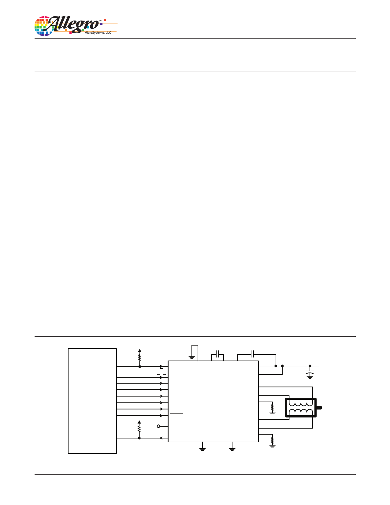
Microcontroller or
Controller Logic
5984-DS, Rev. 1
5V
5 kΩ
5V
5 kΩ
0.1 µF
0.1 µF
SLEEP ROSC CP1 CP2 VCP VBB1
STEP
MS1
MS2
MS3
DIR
ENABLE
RESET
VREF
nFAULT
A5984
VBB2
OUT1A
OUT1B
SENSE1
GND
OUT2A
PAD
OUT2B
SENSE2
Typical Application Diagram
100 µF
1 page 
A5984
DMOS Microstepping Driver with Translator
and Overcurrent Protection
Pinout Diagrams and Terminal List Table
OUT2B
ENABLE
GND
CP1
CP2
VCP
1
2
3
4
5
6
PAD
18 OUT1B
17 DIR
16 GND
15 REF
14 STEP
13 MS3
OUT2B
NC
VBB2
NC
ENABLE
GND
CP1
CP2
1
2
3
4
5
6
7
8
24 OUT1B
23 NC
22 VBB1
PAD 21 NC
20 DIR
19 GND
18 REF
17 STEP
CP1 1
CP2 2
VCP 3
nFAULT 4
MS1 5
MS2 6
RESET 7
ROSC 8
SLEEP 9
MS3 10
STEP 11
REF 12
PAD
24 GND
23 ENABLE
22 OUT2B
21 VBB2
20 SENSE2
19 OUT2A
18 OUT1A
17 SENSE1
16 VBB1
15 OUT1B
14 DIR
13 GND
ES Package Pinouts
ET Package Pinouts
LP Package Pinouts
Terminal List Table
Name
Number
ES ET* LP
Description
CP1 4 7 1 Charge pump capacitor terminal
CP2 5 8 2 Charge pump capacitor terminal
DIR 17 20 14 Logic input
¯E¯ ¯N¯ ¯A¯ ¯B¯ ¯L¯ ¯E¯
2
5 23 Logic input
nFAULT
7
10
4 Fault output, active low
GND
3, 16
6, 19
13, 24 Ground
MS1
8
11
5 Logic input
MS2
9
12
6 Logic input
MS3
13
16
10 Logic input
NC
–
2, 4, 21, 23,
26, 28, 29, 31
–
No connection
OUT1A
21
27
18 DMOS Full Bridge 1 Output A
OUT1B
18
24
15 DMOS Full Bridge 1 Output B
OUT2A
22
30
19 DMOS Full Bridge 2 Output A
OUT2B
1
1 22 DMOS Full Bridge 2 Output B
REF
15
18
12 Gm reference voltage input
¯R¯ ¯E¯ ¯S¯ ¯E¯ ¯T¯
10
13
7 Logic input
ROSC
11
14
8 Timing set
SENSE1
20
25
17 Sense resistor terminal for Bridge 1
SENSE2
23
32
20 Sense resistor terminal for Bridge 2
¯S¯ ¯L¯ ¯E¯ ¯E¯ ¯P¯
12
15
9 Logic input
STEP
14
17
11 Logic input
VBB1
19
22
16 Load supply
VBB2
24
3
21 Load supply
VCP
6
9
3 Reservoir capacitor terminal
PAD
–
–
– Exposed pad for enhanced thermal dissipation*
*The GND pins must be tied together externally by connecting to the PAD ground plane under the device.
Allegro MicroSystems, LLC
5
115 Northeast Cutoff, Box 15036
Worcester, Massachusetts 01615-0036 (508) 853-5000
www.allegromicro.com
5 Page 
A5984
DMOS Microstepping Driver with Translator
and Overcurrent Protection
Slow Mixed
Decay Decay
Slow Mixed
Decay Decay
Slow
Decay
Mixed
Decay
Slow Mixed
Decay Decay
Missed
Step
Step input 10 V/div.
t → , 1 s/div.
Figure 3: Missed Steps in Low-Speed Microstepping
ILOAD 500 mA/div.
Mixed Decay
No Missed
Steps
Step input 10 V/div.
t → , 1 s/div.
Figure 4: Continuous Stepping Using APFD (ROSC Pin Grounded)
Allegro MicroSystems, LLC
11
115 Northeast Cutoff, Box 15036
Worcester, Massachusetts 01615-0036 (508) 853-5000
www.allegromicro.com
11 Page | ||
| Páginas | Total 28 Páginas | |
| PDF Descargar | [ Datasheet A5984.PDF ] | |
Hoja de datos destacado
| Número de pieza | Descripción | Fabricantes |
| A5984 | DMOS Microstepping Driver | Allegro MicroSystems |
| A5985 | DMOS Microstepping Driver | Allegro |
| A5988 | Quad DMOS Full-Bridge PWM Motor Driver | Allegro MicroSystems |
| Número de pieza | Descripción | Fabricantes |
| SLA6805M | High Voltage 3 phase Motor Driver IC. |
Sanken |
| SDC1742 | 12- and 14-Bit Hybrid Synchro / Resolver-to-Digital Converters. |
Analog Devices |
|
DataSheet.es es una pagina web que funciona como un repositorio de manuales o hoja de datos de muchos de los productos más populares, |
| DataSheet.es | 2020 | Privacy Policy | Contacto | Buscar |