|
|
|
PDF MAX270 Data sheet ( Hoja de datos )
| Número de pieza | MAX270 | |
| Descripción | Dual 2nd-Order Continuous Lowpass Filter | |
| Fabricantes | Maxim Integrated | |
| Logotipo | ||
Hay una vista previa y un enlace de descarga de MAX270 (archivo pdf) en la parte inferior de esta página. Total 16 Páginas | ||
|
No Preview Available !
MAX270/MAX271
Digitally-Programmed, Dual
2nd-Order Continuous Lowpass Filter
General Description
The MAX270/MAX271 are digitally-programmed, dual
second-order continuous-time lowpass filters. Their typi-
cal dynamic range of 96dB surpasses most switched
capacitor filters which require additional filtering to
remove clock noise. The MAX270/MAX271 are ideal for
anti-aliasing and DAC smoothing applications and can
be cascaded for higher-order responses.
The two filter sections are independently programmable
by either microprocessor (FP) control or pin strapping.
Cutoff frequencies in the 1kHz to 25kHz range can be
selected.
The MAX270 has an on-board, uncommitted op amp,
while the MAX271 has an internal track-and-hold (T/H).
Applications
Lowpass Filtering
Anti-Aliasing Filter
Output Smoothing
Low-Noise Applications
Anti-Aliasing and Track-and-Hold (MAX271)
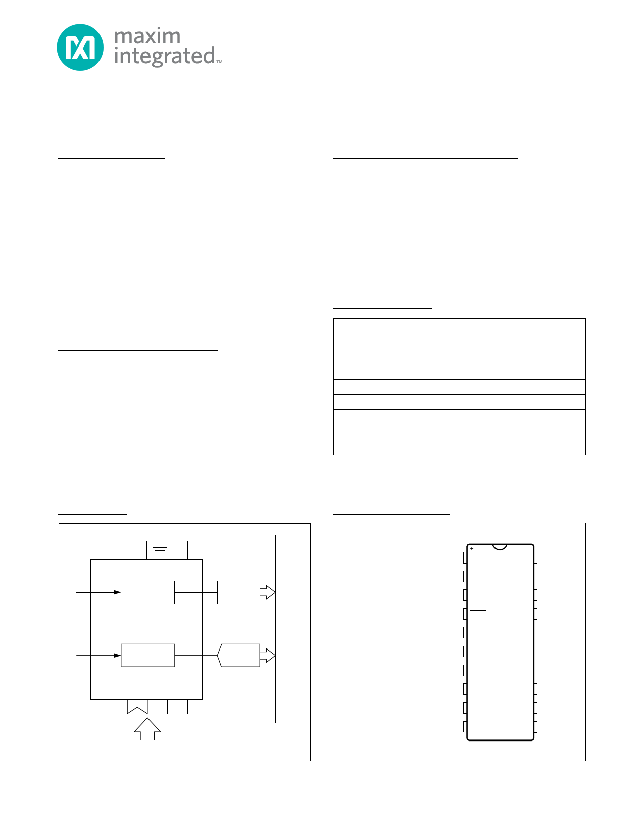
Typical Operating Circuit
Features
S Continuous-Time Filtering - No Clock Required
S Dual 2nd-Order Lowpass Filters
S Sections Independently Programmable: 1kHz to
25kHz
S 96dB Dynamic Range
S No External Components
S Cascadable for Higher Order
S Low-Power Shutdown Mode
S Track-and-Hold (MAX271)
Ordering Information
PART
MAX270CPP
MAX270CWP
MAX270EPP
MAX270EWP
MAX271CNG
MAX271CWG
MAX271ENG
MAX271EWG
TEMP RANGE
0NC to +70NC
0NC to +70NC
-40NC to +85NC
-40NC to +85NC
0NC to +70NC
0NC to +70NC
-40NC to +85NC
-40NC to +85NC
PIN-PACKAGE
20 PDIP
20 Wide SO
20 PDIP
20 Wide SO
20 PDIP
20 Wide SO
20 PDIP
20 Wide SO
Devices are available in a lead(Pb)-free/RoHS-compliant package.
Specify lead-free by adding a plus (+) to the part number when
ordering.
Pin Configurations
+5V -5V
TOP VIEW
V+
IN INA
GND
FILTER A
ANTI-ALIASING
MAX270
V-
OUTA
OUT OUTB
AO
FILTER B
INB
ANTI-ALIASING
D0-D6
CS WR
A/D WITH
T/H
DAC
DSB
µP OR PIN-STRAP CONTROL
Pin Configurations
continued at end
of data sheet.
1 OP OUT
OP IN 20
2 V+
D6 19
3 OUTA
D5 18
4 SHDN
D4 17
MAX270
5 INA
D3 16
6 V-
D2 15
7 INB
D1 14
8 OUTB
D0 13
9 GND
A0 12
10 WR
CS 11
PDIP/SO(W)
For pricing, delivery, and ordering information, please contact Maxim Direct
at 1-888-629-4642, or visit Maxim’s website at www.maximintegrated.com.
19-3701; Rev 2; 1/12
1 page 
MAX270/MAX271
Digitally-Programmed, Dual
2nd-Order Continuous Lowpass Filter
Typical Operating Characteristics (continued)
CASCADED FILTER GAIN vs. FREQUENCY
(NORMALIZED TO CUTOFF FREQUENCY)
+0.5
CASCADED FILTER GAIN vs. FREQUENCY
(NORMALIZED TO CUTOFF FREQUENCY)
0
FILTER HARMONIC DISTORTION
0
-0.5
-1.5
-2.5
-3.5
-4.5
-5.5
-6.5
-7.5
0.01
V+ = +5V
V- = -5V
fC (FILTER A) = fC (FILTER B) =
0-127 (1-25kHz TYP)
FILTERS A AND B CASCADED
FIGURE 5
TA = +25˚C
0.1
fIN/fC
1.0
FILTER TOTAL HARMONIC DISTORTION
PLUS NOISE vs.INPUT FREQUENCY
fIN
(Hz)
fC
CODE
fC
(Hz)
(TYP)
THD PLUS
NOISE
(TYP)
190 0 1k -78
-20
-40 V+ = +5V
V- = -5V
fC (FILTER A) = fC (FILTER B) =
-60
0-127 (1-25kHz TYP)
FILTERS A AND B CASCADED
FIGURE 5
-80 TA = +25˚C
0.01 1.0
fIN/fC
10
FILTER TOTAL HARMONIC DISTORTION
PLUS NOISE vs. INPUT AMPLITUDE
-60
V+ = +5V
-65
V- = -5V
fIN = 390.625Hz
fC CODE = 44 (2.01kHz TYP)
-70 TA = +25˚C
-20
V+ = +5V
V- = -5V
-40 fC CODE = 44 (2.01kHz TYP)
fTEST = 390.625Hz
-60 TA = +25˚C
VIN = 3.5VP-P
-80
-100
-120
0
1k 2k 3k
F (Hz)
4k
MAX271 FILTER PLUS TRACK-AND-HOLD
SPURIOUS-FREE DYNAMIC RANGE
vs. INPUT FREQUENCY
fIN
(Hz)
fC
CODE
fC
(Hz)
(TYP)
SFDR
(dB)
195 0
1k 73.5
390 44 2.01k -73
-75
781
72
4.01k
69.5
1367 100 7.01k
-67
4875 127
25k
-66
V+ = 5V, V- = -5V; VIN = 3.5VP-P; TA = +25˚C
-80
-85
0.2
1.0
VIN (VP-P)
1562.5
105
8.08k
66
3906
124
19.4k
61.5
8.0 V+ = 5V, V- = -5V; VIN = 3.5VP-P;
T/H SWITCHED AT 50kHz, 50% DUTY CYCLE; TA = +25˚C
MAX271 FILTER PLUS TRACK-AND-HOLD
SPURIOUS-FREE DYNAMIC RANGE
vs. INPUT AMPLITUDE
MAX271 FILTER PLUS TRACK-AND-HOLD
SPURIOUS-FREE DYNAMIC RANGE
vs. SAMPLING FREQUENCY
55 V+ = +5V
V- = -5V
fIN = 390Hz
fC CODE = 44 (2.01kHz TYP)
65 TA = +25˚C
fSAMPLE fIN fC fC SFDR
(Hz) (Hz) CODE (Hz) (dB)
100k 781 72 4.01k 72
75
-85
0.5
Maxim Integrated
1.0
VIN (VP-P)
8.0
200k 1562 105 8.08k 72
500k 3906 124 19.4k 64
V+ = 5V, V- = -5V; VIN = 3.5VP-P;
T/H SWITCHED AT 50kHz, 50% DUTY CYCLE; TA = +25˚C
5
5 Page 
MAX270/MAX271
Digitally-Programmed, Dual
2nd-Order Continuous Lowpass Filter
MAX270 Control Interlace
The A0 pin is a three-level input that selects the memory
addresses for updating cutoff frequency data in FP mode:
A0
Logic Low
Logic High
SELECTS
Filter B
Filter A
Figure 2 shows µP-mode interface timing.
Connecting A0 to the negative supply selects pin-strap
mode. Pin-strap mode allows filter programming with
no timing requirements. Internal memory latches are
disabled, permitting filters A and B to be programmed
directly to fC data strapped on D0–D6. This mode dis-
ables CS and WR controls, and filters A and B are pro-
grammed to the same fC.
A low level on the SHDN pin shuts down all amplifiers
and disconnects OUTA, OUTB, and OP OUT. Current
consumption drops to less than 15µA in this mode.
MAX271 Control Interlace
Connecting the MODE pin to GND or V- selects the
µP mode. In this mode, addressable program memory
controls filter cutoff frequency programming and all T/H
functions, except T/H. See the Figure 2 for timing charac-
teristics. Table 2 describes available functions:
tWS
CS
tWH
tWR
WR
ADDRESS
(A0, A1)
DATA
(D0-D6)
tAS
tDS
tAH
tDH
NOTE : ALL DIGITAL INPUTS ARE LEVEL-SENSITIVE. WHEN WR AND CS ARE BOTH LOW,
THE DATA INPUT LATCHES ARE TRANSPARENT. AND THE FILTERS ARE
PROGRAMMED TO THE DATA ON D0–D6
Figure 2. MAX270/MAX271 Digital Timing Diagram
In FP mode, SHDN, T/H A/B, and T/H EN pins are dis-
abled. T/H remains enabled and performs the T/H track-
ing/holding function.
Tying MODE to V+ selects pin-strap mode. In this mode,
both memory latches are transparent, and data on D0–D6
controls the fC of filters A and 8 directly (filters A and 8
are programmed to the same fC). Pin strap D0–D6 for
operation without FP. A0, A1, CS, and WR are disabled.
Table 2. MAX271 µP-Mode Interface
A1 A0 06 05 04 03
02 01 D0
FUNCTION
00
7-bit fC data
Selects filter A
01
7-bit fC data
Selects filter B
1 0 X XX X
X X 0 T/H OUT disabled
1 0 X XX X
X X 1 T/H OUT enabled
1 0 X XX X
X 0 X Selects OUTB as input to T/H
1 0 X XX X
X 1 X Selects OUTA as input to T/H
1 1 X XX X
X
X
0
Filter shutdown mode. All outputs floated, 15μA
max supply current
11
X = Don't care
X
XX
X
X X 1 Removes filter from shutdown mode
Maxim Integrated
11
11 Page | ||
| Páginas | Total 16 Páginas | |
| PDF Descargar | [ Datasheet MAX270.PDF ] | |
Hoja de datos destacado
| Número de pieza | Descripción | Fabricantes |
| MAX270 | Dual 2nd-Order Continuous Lowpass Filter | Maxim Integrated |
| MAX2700 | 1.8GHz to 2.5GHz Direct Downconversion Receivers | Maxim Integrated |
| MAX2701 | 2.1 GHz to 2.5 GHz direct downconversion receiver | Maxim Integrated |
| MAX271 | Dual 2nd-Order Continuous Lowpass Filter | Maxim Integrated |
| Número de pieza | Descripción | Fabricantes |
| SLA6805M | High Voltage 3 phase Motor Driver IC. |
Sanken |
| SDC1742 | 12- and 14-Bit Hybrid Synchro / Resolver-to-Digital Converters. |
Analog Devices |
|
DataSheet.es es una pagina web que funciona como un repositorio de manuales o hoja de datos de muchos de los productos más populares, |
| DataSheet.es | 2020 | Privacy Policy | Contacto | Buscar |