|
|
|
PDF UT54ACTS540 Data sheet ( Hoja de datos )
| Número de pieza | UT54ACTS540 | |
| Descripción | Octal Buffers & Line Drivers | |
| Fabricantes | Aeroflex Circuit Technology | |
| Logotipo | ||
Hay una vista previa y un enlace de descarga de UT54ACTS540 (archivo pdf) en la parte inferior de esta página. Total 10 Páginas | ||
|
No Preview Available !
Standard Products
UT54ACS540/UT54ACTS540
Octal Buffers & Line Drivers, Inverted Three-State Outputs
Datasheet
November 2010
www.aeroflex.com/logic
FEATURES
Three-state outputs drive bus lines or buffer memory address
registers
1.2μ CMOS
- Latchup immune
High speed
Low power consumption
Single 5 volt supply
Available QML Q or V processes
Flexible package
- 20-pin DIP
- 20-lead flatpack
UT54ACS540 - SMD 5962-96592
UT54ACTS540 - SMD 5962-96593
DESCRIPTION
The UT54ACS540 and the UT54ACTS540 are inverting octal
buffers and line drivers which improve the performance and
density of three-state memory address drivers, clock drivers, and
bus-oriented receivers and transmitters.
The devices are characterized over full military temperature
range of -55°C to +125°C.
FUNCTION TABLE
INPUTS
OUTPUT
1G 2G An Yn
L L LH
L LHL
HXXZ
XHXZ
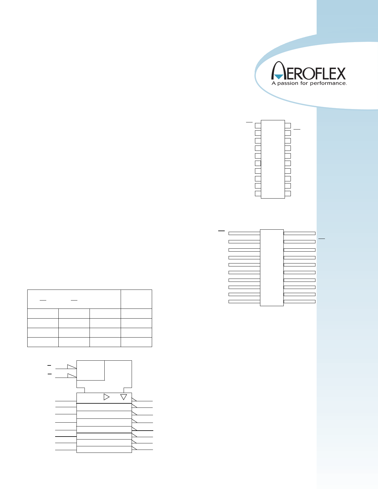
LOGIC SYMBOL
1G (1)
2G (19)
&
EN
PINOUTS
1G
A1
A2
A3
A4
A5
A6
A7
A8
VSS
A1 (2)
A2 (3)
A3 (4)
A4 (5)
A5 (6)
A6 (7)
A7 (8)
A8 (9)
(18)
Y1
(17) Y2
(16) Y3
(15) Y4
(14) Y5
(13) Y6
(12) Y7
(11) Y8
Note:
1. Logic symbol in accordance with ANSI/IEEE Std 91-1984 and IEC
Publication 617-12.
1
20-Pin DIP
Top View
1G 1 20 VDD
A1 2 19 2G
A2 3 18 Y1
A3 4 17 Y2
A4 5 16 Y3
A5 6 15 Y4
A6 7 14 Y5
A7 8 13 Y6
A8 9 12 Y7
VSS 10 11 Y8
20-Lead Flatpack
Top View
1 20
2 19
3 18
4 17
5 16
6 15
7 14
8 13
9 12
10 11
VDD
2G
Y1
Y2
Y3
Y4
Y5
Y6
Y7
Y8
1 page 
Notes:
1. Functional tests are conducted in accordance with MIL-STD-883 with the following input test conditions: VIH = VIH(min) + 20%, - 0%; VIL = VIL(max) + 0%, -
50%, as specified herein, for TTL, CMOS, or Schmitt compatible inputs. Devices may be tested using any input voltage within the above specified range, but are
guaranteed to VIH(min) and VIL(max).
2. Supplied as a design limit but not guaranteed or tested.
3. Per MIL-PRF-38535, for current density ≤ 5.0E5 amps/cm2, the maximum product of load capacitance (per output buffer) times frequency should not exceed 3,765
pF/MHz.
4. Not more than one output may be shorted at a time for maximum duration of one second.
5. Capacitance measured for initial qualification and when design changes may affect the value. Capacitance is measured between the designated terminal and VSS at
frequency of 1MHz and a signal amplitude of 50mV rms maximum.
6. Maximum allowable relative shift equals 50mV.
7. All specifications valid for radiation dose ≤ 1E6 rads(Si).
8. Power does not include power contribution of any TTL output sink current.
9. Power dissipation specified per switching output.
10. This value is guaranteed based on characterization data, but not tested.
5
5 Page | ||
| Páginas | Total 10 Páginas | |
| PDF Descargar | [ Datasheet UT54ACTS540.PDF ] | |
Hoja de datos destacado
| Número de pieza | Descripción | Fabricantes |
| UT54ACTS54 | 4-Wide AND-OR-INVERT Gates | Aeroflex Circuit Technology |
| UT54ACTS540 | Octal Buffers & Line Drivers | Aeroflex Circuit Technology |
| UT54ACTS541 | Octal Buffers and Line Drivers | ETC |
| UT54ACTS541 | Octal Buffers & Line Drivers | Aeroflex Circuit Technology |
| Número de pieza | Descripción | Fabricantes |
| SLA6805M | High Voltage 3 phase Motor Driver IC. |
Sanken |
| SDC1742 | 12- and 14-Bit Hybrid Synchro / Resolver-to-Digital Converters. |
Analog Devices |
|
DataSheet.es es una pagina web que funciona como un repositorio de manuales o hoja de datos de muchos de los productos más populares, |
| DataSheet.es | 2020 | Privacy Policy | Contacto | Buscar |