|
|
|
PDF AAT4601 Data sheet ( Hoja de datos )
| Número de pieza | AAT4601 | |
| Descripción | 1.8A Current Limited P-Channel Switch | |
| Fabricantes | Skyworks | |
| Logotipo | ||
Hay una vista previa y un enlace de descarga de AAT4601 (archivo pdf) en la parte inferior de esta página. Total 13 Páginas | ||
|
No Preview Available !
General Description
The AAT4601 SmartSwitch is a member of Skyworks'
Application Specific Power MOSFET™ (ASPM™) product
family. It is a 1.8A current limited P-channel MOSFET
power switch designed for high-side load switching appli-
cations. This switch operates with inputs ranging from
2.7V to 5.5V, making it ideal for both 3V and 5V systems.
An integrated current-limiting circuit protects the input
supply against large changes in load current which could
cause the supply to fall out of regulation. The AAT4601
has protection from thermal overload which limits power
dissipation and junction temperatures. The maximum
current limit level will guarantee that 1.8A can be deliv-
ered to the load; the actual threshold is programmed
with a resistor from the SET pin to ground. The quiescent
supply current is typically 12μA. In shutdown mode, the
supply current decreases to less than 1μA.
The AAT4601 is available in a Pb-free, 8-pin SOP pack-
age and is specified over the -40°C to +85°C tempera-
ture range.
DATA SHEET
AAT4601
1.8A Current Limited P-Channel Switch
Features
• Input Voltage: 2.7V to 5.5V
• Programmable Over-Current Threshold
• Low Quiescent Current
▪ 12μA Typical
▪ Less Than 1μA with Switch Off
• Only 2.5V Needed for ON Control
• Thermal Shutdown
• Fault Flag
• 2ms Fault Blanking
• Under-Voltage Lockout
• Temperature Range: -40°C to +85°C
• 4kV ESD Rating
• UL Approved—File No. E217765
• 8-Pin SOP Package
Applications
• Hot Swap Supplies
• Notebook Computers
• Peripheral Ports
• USB Ports
UL Recognized Component
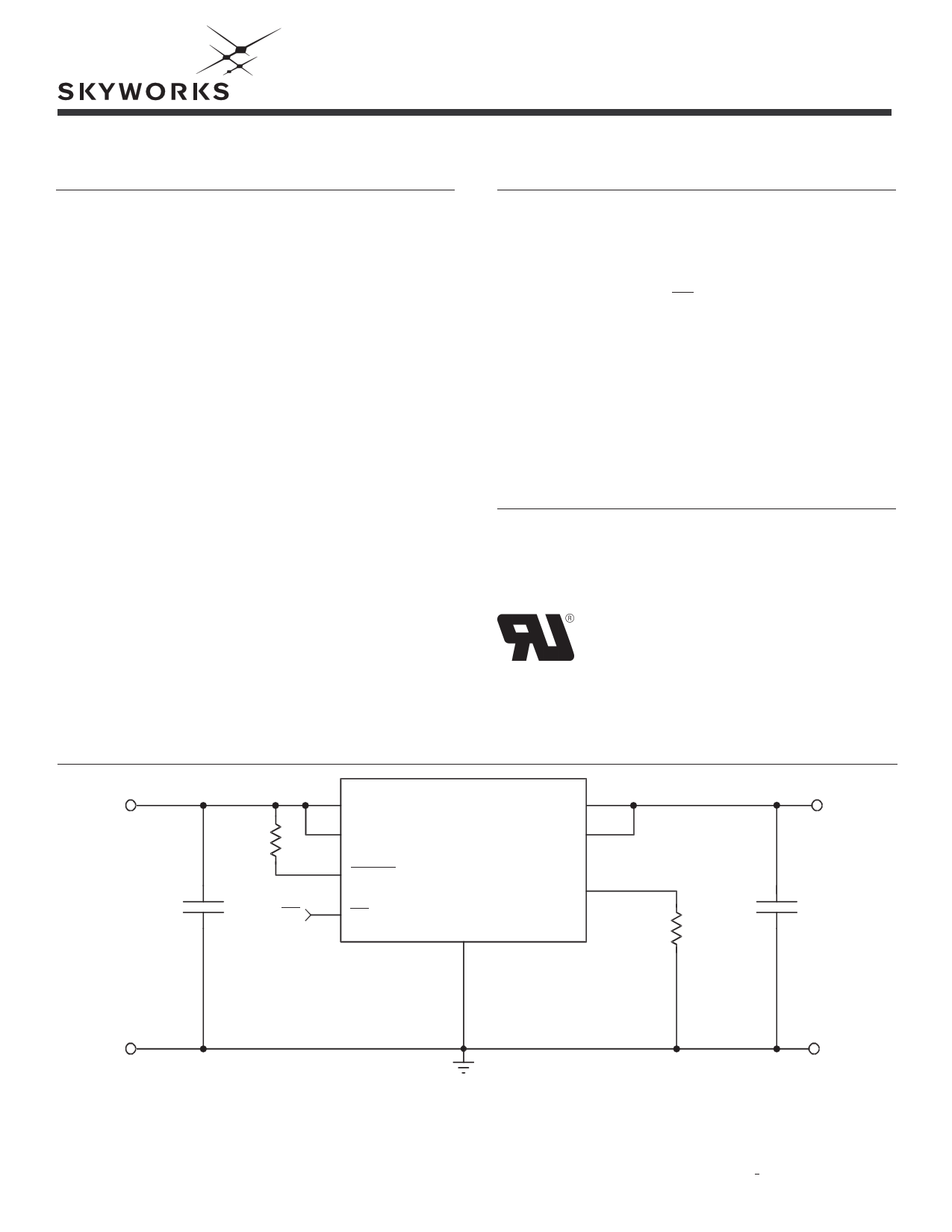
Typical Application
INPUT
100kΩ
1μF ON
1
IN
2
IN
8 FAULT
AAT4601
3
ON
GND
4
6
OUT
7
OUT
5
SET
RSET
OUTPUT
1μF
Skyworks Solutions, Inc. • Phone [781] 376-3000 • Fax [781] 376-3100 • [email protected] • www.skyworksinc.com
201913A • Skyworks Proprietary Information • Products and Product Information are Subject to Change Without Notice. • May 3, 2012
1
1 page 
Typical Characteristics
Unless otherwise noted, VIN = 5V, TA = 25°C.
Quiescent Current vs. Temperature
25
20
15
10
5
0
-40
-20
0 20 40 60 80
Temperature (°C)
100 120
DATA SHEET
AAT4601
1.8A Current Limited P-Channel Switch
Quiescent Current
25
20
15
10
5
0
0123456
Input Voltage (V)
1.0
0.8
0.6
0.4
0.2
0
0
Current Limit
(RSET = 2kΩ; VIN = 5V)
12 3 4
Output Voltage (V)
5
Off-Supply Current vs. Temperature
10
1
0.1
0.01
0.001
0.0001
-40
-20
0
20 40 60 80 100 120 140
Temperature (°C)
25000
24000
23000
22000
21000
20000
19000
18000
0.0
RSET * ILIM Product vs. ILIM
0.5 1.0 1.5
Typical I LIM (A)
2.0
2.5
Off-Switch Current vs. Temperature
10
1
0.1
0.01
0.001
0.0001
-40 -20
0
20 40 60 80 100 120 140
Temperature (°C)
Skyworks Solutions, Inc. • Phone [781] 376-3000 • Fax [781] 376-3100 • [email protected] • www.skyworksinc.com
201913A • Skyworks Proprietary Information • Products and Product Information are Subject to Change Without Notice. • May 3, 2012
5
5 Page 
Input Capacitor
The input capacitor serves two purposes. First, it pro-
tects the source power supply from transient current
effects generated by the application load circuit. If a
short circuit is suddenly applied to the output of an
AAT4601, there is a microsecond-long period during
which a large current can flow before the current limit
circuitry activates; refer to the characteristic curve,
“Short-Circuit Through 0.3." A properly sized input
capacitor can dramatically reduce the load switch input
transient response effects seen by the power supply and
other circuitry upstream from the AAT4601.
The second purpose of the input capacitor is to prevent
transient events generated by the load circuit from affect-
ing operation of the AAT4601. For example, if an AAT4601
is used in a circuit that operates from a 3V power supply
with poor step load response, it is possible that turning on
the load switch could cause the input power supply to
droop below the AAT4601's under-voltage lockout thresh-
old. This drop in voltage would cause the AAT4601 to turn
off until the input power supply voltage recovers. Since
this cycle would be self-perpetuating, the entire circuit
could be seen to be unstable. In the very rare case where
capacitor cost is prohibitive, the output load circuit should
be slew rate limited when turned on.
Output Capacitor
In order to insure stability while the device current limit
is active, a small capacitance of approximately 1μF
should be used. When the AAT4601 is activated using
the ON function, there are no momentary current tran-
sients, as in the case when a short circuit is suddenly
applied to a device that is already on; refer to the char-
acteristic curve, “Switch Turn-On Time.” No matter how
big the output capacitor, output current is limited to the
value allowed by the threshold determined by RSET and
the internal current limiting circuitry. This permits very
large output capacitors to be used.
For example, USB ports are specified to have at least
120μF of downstream capacitance from their controlling
power switch. An output capacitance as large as 1000μF
would not disturb the input power supply to the AAT4601
used to control the USB port.
ON Input
When the AAT4601 is in the off state, the output is an
open circuit and the device quiecent current consump-
tion is reduced to less than 1μA. The ON threshold volt-
DATA SHEET
AAT4601
1.8A Current Limited P-Channel Switch
age is set to allow the AAT4601 to be controlled by 5V
TTL levels, as well as CMOS power from 2.5V to 5V. The
ON function control voltage level should not exceed the
input supply level applied to the IN pin.
FAULT Output
A FAULT flag is provided to alert a system if the load
switch is not receiving a sufficient voltage level to prop-
erly operate. If either the current limit or over-tempera-
ture circuits in any combination are active for more than
approximately 2ms continuously, the FAULT pin is pulled
to ground internally through a 100 resistance. The 2ms
delay on the FAULT function is intended to prevent
capacitive loads connected to the load switch output
from activating FAULT when the device is turned on. The
placement of a pull-up resistor between the FAULT pin
and the IN pin is recommended. Reasonable values for
the pull-up resistor should range from 10k to 100k.
Since FAULT is an open drain terminal, it may be pulled
up to any voltage that is not greater than the level pres-
ent on the IN pin. This is done to allow the AAT4601 to
signal ancillary circuitry that is powered by a voltage
level less than the level on the IN pin.
Reverse Voltage
The AAT4601 is designed to control current flowing from
IN to OUT. If a voltage is applied to OUT which is great-
er than that on IN, a large resulting reverse current may
flow, potentially damaging the AAT4601.
Printed Circuit Board
Layout Recommendations
For proper thermal management, and to take advantage
of the low RDS(ON) of the AAT4601, a few circuit board lay-
out rules should be followed: VIN and VOUT should be
routed using wider than normal traces, and GND should
be connected to a ground plane. For best performance,
CIN and COUT should be placed close to the package pins.
Evaluation Board Layout
The AAT4601 evaluation layout follows the printed circuit
board layout recommendations, and can be used for
good applications layout.
Note: Board layout shown is not to scale.
Skyworks Solutions, Inc. • Phone [781] 376-3000 • Fax [781] 376-3100 • [email protected] • www.skyworksinc.com
201913A • Skyworks Proprietary Information • Products and Product Information are Subject to Change Without Notice. • May 3, 2012
11
11 Page | ||
| Páginas | Total 13 Páginas | |
| PDF Descargar | [ Datasheet AAT4601.PDF ] | |
Hoja de datos destacado
| Número de pieza | Descripción | Fabricantes |
| AAT4601 | 1.5A Current Limited P-Channel Switch | Advanced Analogic Technologies |
| AAT4601 | 1.8A Current Limited P-Channel Switch | Skyworks |
| AAT4601A | 1.8A Current Limited P-Channel Switch | Advanced Analogic Technologies |
| AAT4601IAS-B1 | 1.5A Current Limited P-Channel Switch | Advanced Analogic Technologies |
| Número de pieza | Descripción | Fabricantes |
| SLA6805M | High Voltage 3 phase Motor Driver IC. |
Sanken |
| SDC1742 | 12- and 14-Bit Hybrid Synchro / Resolver-to-Digital Converters. |
Analog Devices |
|
DataSheet.es es una pagina web que funciona como un repositorio de manuales o hoja de datos de muchos de los productos más populares, |
| DataSheet.es | 2020 | Privacy Policy | Contacto | Buscar |