|
|
|
PDF HV633 Data sheet ( Hoja de datos )
| Número de pieza | HV633 | |
| Descripción | 128-Level Amplitude Gray-Shade Display Column Driver | |
| Fabricantes | Supertex | |
| Logotipo | ||
Hay una vista previa y un enlace de descarga de HV633 (archivo pdf) en la parte inferior de esta página. Total 12 Páginas | ||
|
No Preview Available !
Supertex inc.
32-Channel, 128-Level Amplitude
Gray-Shade Display
Column Driver
HV633
Features
►►HVCMOS® technology
►►5.0V CMOS inputs
►►Capable of 128 levels of gray shading
►►Modulation voltage up to +80V
►►24MHz data throughput rate
►►32 outputs per device (can be cascaded)
►►Pin-programmable shift direction (DIR)
►►D/A conversion cycle time is 20µs
►►Diodes in output structure allow usage in energy
recovery systems
►►Available in 3-sided 64-lead gull wing package
Applications
►►Electroluminescent Displays
►►Polycholesteric Displays
General Description
The HV633 is a 32-channel driver IC for gray shade display
use. It is designed to produce varying output voltages between
3.0 - 80V. This amplitude modulation at the output is facilitated
by an external ramp voltage VR. See Theory of Operation for
detailed explanation.
This device consists of dual 16-bit shift registers, 32 data
latches and comparators, and control logic to preform 128
levels of gray shading. There are 7 bits of data inputs. Data is
shifted through the shift registers at both edges of the clock,
resulting in a data transfer rate of twice that of the shift clock
frequency. When the DIR pin is high, CSI/CSO is the input/
output for the chip select pulse. When DIR is low, CSI/CSO is
the output/input for the chip select pulse. When the DIR pin is
high, it allows the HV633 to shift data in the counter-clockwise
direction when viewed from the top of the package. When the
DIR pin is low, data is shifted in the clockwise direction. The
output circuitry allows the energy which is stored in the output
capacitance to be returned to VPP through the body diode of
the output transistor.
Functional Block Diagram
VDD
VR VPP
CSI
SC
LC
CC
CSO
DIR
7
D1 - D7
Low Voltage
Shift Register
Latches
Comparator
Counter
High Voltage
32 Source Follower
Output Buffer
IBIAS Control
HVOUT1
~~
HVOUT32
VCTL RCTL
Doc.# DSFP-HV633
C031414
Supertex inc.
www.supertex.com
1 page 
Functional Block Diagram
1
VCTL
RCTL
2
Dual
●
16-bit
Shift Registers ●
●
31
DIR I/O
Buffers
CSI
32
SC
SC
I/O
Buffers
CSO
L/E Data
Latches
L/E Data
Latches
7
7
●
● ●●
● ●●●
● ●●
●
L/E Data
Latches
7
L/E Data
Latches
7
Shift
Clock
Buffer
Data In
Buffers
SC D7 ● ● ● ● ● ● ● D1
Latches and 7
Comparators
Latches and 7
Comparators
Latches and 7
Comparators
Latches and 7
Comparators
7
CC
Count
Clear
Pulse
Generator
Load
Note:
SC = Shift Clock, LC = Load Count, CC = Count Clock, CSI = Chip Select Input, CSO = Chip Select Output
*Data rate = 2x the SC frequency
HV633
See Output Stage Detail
GND
VR VPP
RS
F/F
Output
Stage
HVOUT1
RS
F/F
Output
Stage
HVOUT2
●
●
●
RS
F/F
Output
Stage
HVOUT31
RS
F/F
Output
Stage
HVOUT32
Counter
Reset
Counter
Load
Count
Buffer
Count
Clock
Buffer
LC CC
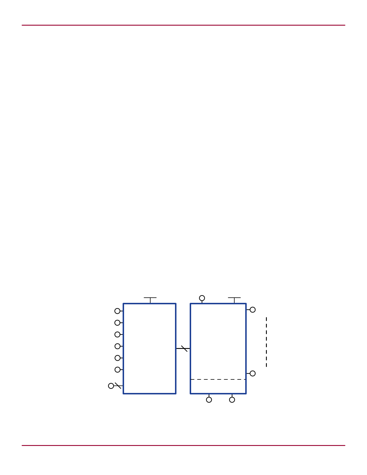
Input and Output Equivalent Circuits
VDD
VDD
DATA
IN
DATA
OUT
LVGND
Logic Inputs
LVGND
Logic Data Output
Output Stage Detail
VCTL
RCTL
VR
CH
Internal
Logic
&
Bias
Circuit
VPP
Q1
HVOUT
Q2
Doc.# DSFP-HV633
C031414
5
Supertex inc.
www.supertex.com
5 Page 
Pin Descriptions (cont.)
Pin #
Function
30 D7
31 D6
32 D5
33 D4
34 D3
35 D2
36 D1
37 NC
38 LVGND
39 NC
40
LC
(Load Count)
41 NC
42
CC
(Count Clock)
43 CSO
44 NC
45 VPP
46 NC
47 VR
48 HVGND
49 HVOUT17
50 HVOUT18
51 HVOUT19
52 HVOUT20
53 HVOUT21
54 HVOUT22
55 HVOUT23
56 HVOUT24
57 HVOUT25
58 HVOUT26
59 HVOUT27
60 HVOUT28
61 HVOUT29
62 HVOUT30
63 HVOUT31
64 HVOUT32
Description
HV633
Inputs for binary-format parallel data.
No connect.
This is ground for the logic section. HVGND and LVGND should be connected together
externally.
No connect.
Input for a pulse whose rising edge causes data from the input latches to enter the
comparator latches, and whose falling edge initiates the conversion of this binary data to
an output level (D-to-A). Also, the HVOUT will clear to zero after the load count is initiated.
No connect.
Input to the count clock generator whose increments are compared to the data in the
comparator latches.
Input pin for the chip select pulse (when DIR is low). Output pin for the chip select pulse
(when DIR is high).
No connect.
This input biases the output source followers.
No connect.
High-voltage ramp input for charging the output stage hold capacitors (CH).This input can
be linear or non-linear as desired.
This is ground for the high-voltage (output) section. HVGND and LVGND should be
connected together externally.
High-voltage outputs
Doc.# DSFP-HV633
C031414
Supertex inc.
11 www.supertex.com
11 Page | ||
| Páginas | Total 12 Páginas | |
| PDF Descargar | [ Datasheet HV633.PDF ] | |
Hoja de datos destacado
| Número de pieza | Descripción | Fabricantes |
| HV632 | 256 Gray-Shade High Voltage Driver | Supertex |
| HV632PG-G | 256 Gray-Shade High Voltage Driver | Supertex |
| HV633 | 128-Level Amplitude Gray-Shade Display Column Driver | Supertex |
| HV633PG-G | 128-Level Amplitude Gray-Shade Display Column Driver | Supertex |
| Número de pieza | Descripción | Fabricantes |
| SLA6805M | High Voltage 3 phase Motor Driver IC. |
Sanken |
| SDC1742 | 12- and 14-Bit Hybrid Synchro / Resolver-to-Digital Converters. |
Analog Devices |
|
DataSheet.es es una pagina web que funciona como un repositorio de manuales o hoja de datos de muchos de los productos más populares, |
| DataSheet.es | 2020 | Privacy Policy | Contacto | Buscar |