|
|
|
PDF XR22802 Data sheet ( Hoja de datos )
| Número de pieza | XR22802 | |
| Descripción | Hi-Speed USB to 10/100 Ethernet Bridge | |
| Fabricantes | Exar | |
| Logotipo | ||
Hay una vista previa y un enlace de descarga de XR22802 (archivo pdf) en la parte inferior de esta página. Total 30 Páginas | ||
|
No Preview Available !
XR22802
Hi-Speed USB to 10/100 Ethernet Bridge
General Description
The XR22802 is a Hi-Speed USB 2.0 compound device with an embed-
ded hub and 5 downstream USB functions: 10/100 Ethernet MAC and
PHY, 2 UARTs, multi-master capable I2C controller, and an Enhanced
Dedicated GPIO Entity (EDGE) controller.
The upstream USB interface has an integrated USB 2.0 PHY and device
controller that is compliant with both Hi-Speed (480Mbps) and Full-Speed
(12Mbps) USB 2.0. The vendor ID, product ID, power mode, remote
wakeup support and maximum power consumption are amongst the val-
ues that can be programmed using the on-chip One-Time Programmable
(OTP) memory.
The 10/100 Ethernet MAC and PHY is compliant with IEEE 802.3 and
supports auto-negotiation, auto-MDIX, checksum offload, auto-polarity
correction in 10Base-T and remote wakeup capabilities.
The enhanced UART has a maximum data rate of 15 Mbps. Using a frac-
tional baud rate generator, any baud rate between 300 bps and 15 Mbps
can be accurately generated. In addition, the UART has a large 1024-byte
TX FIFO and RX FIFO to optimize the overall data throughput for various
applications. The automatic RS485 control feature simplifies both the
hardware and software for half-duplex RS-485 applications. If required,
the multidrop (9-bit) mode feature further simplifies typical multidrop appli-
cations by enabling / disabling the UART receiver depending on the
address byte received.
The multi-master capable I2C controller and EDGE controller (up to 32
GPIOs) can be accessed via the USB HID interface. The EDGE pins or
I2C interface can be used for controlling and monitoring other peripherals.
Up to 2 EDGE pins can be configured as a PWM generator.
FEATURES
USB 2.0 Compliant Interface
10/100 Ethernet MAC and PHY
Enhanced UART
I2C Multi-master
Enhanced Dedicated GPIO Entity (EDGE)
Single +5.0V Power Supply Input
Regulated +3.3V Output Power
Single 25MHz Crystal
±15kV HBM ESD Protection on USB data
pins
±8kV HBM ESD Protection on all other pins
USB CDC-ACM, CDC-ECM and HID
compliant
Custom Software Drivers
APPLICATIONS
USB to Ethernet Dongles
POS Terminals
Test Instrumentation
Networking
Factory Automation and Process Controls
Industrial Applications
Ordering Information – Back Page
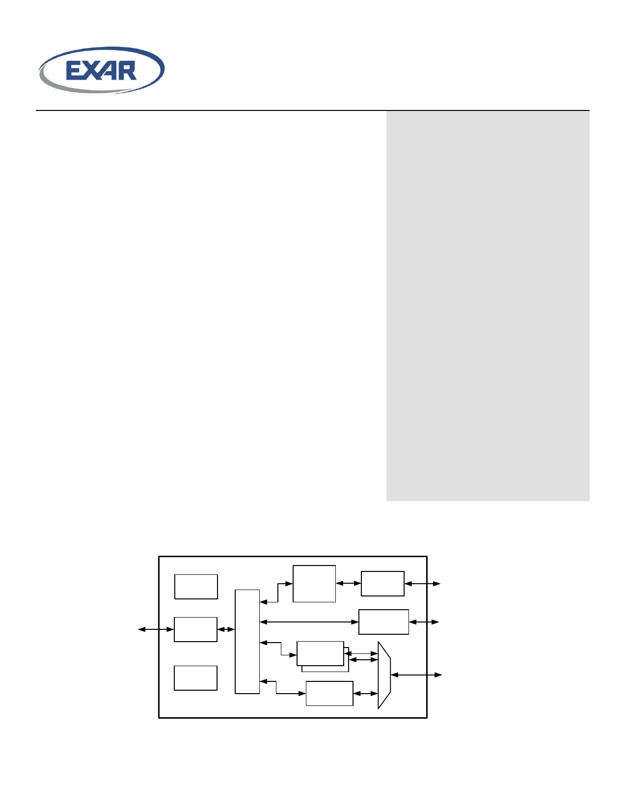
Block Diagram
USB
25 MHz
XO
Upstream
USB Phy
OTP
Memory
USB
2.0
Hub
10/100
Ethernet
MAC
UART Ch A /
Modem IO
Ethernet
Phy
I2C
Multimaster
EDGE
Controller
Ethernet
I2C
UART Ch.
A, B
/ EDGE
© 2015 Exar Corporation
1 / 46
exar.com/XR22802
Rev 1B
1 page 
Pin Configuration
XR22802
E30 1
E31 2
VBUS_SENSE 3
REXT 4
E29 5
E28 6
CAP1 7
GND 8
USBD- 9
USBD+ 10
VCC 11
E26 12
ETH_SPD 13
E27 14
Exar
XR22802
E_PAD
42 E7/TXA
41 E6/RXA/RWKA#
40 GND
39 E9/CDB#/GB1
38 E8/RIB#/RWKB#/GB0
37 E18
36 GND
35 CAP2
34 E19
33 ETH_LINK
32 E16
31 E17
30 E1/CDA#/GA1
29 E0/RIA#/RWKA#/GA0
Pin Assignments
Pin No.
Pin Name
1 E30
2 E31
3 VBUS_SENSE
4 REXT
5 E29
6 E28
7 CAP1
© 2015 Exar Corporation
Top View
Type
I/O
I/O
I
I
I/O
I/O
I
Description
Enhanced general purpose IO
Enhanced general purpose IO
VBUS Sense input. In self-powered mode, the VBUS from the USB connector needs to be
connected to this pin through a voltage divider circuit (VBUS = 5V, VBUS_SENSE = 3.3V
input) using large resistance values to minimize power. It should also be decoupled by a
0.1uF capacitor. This feature may be enabled via the OTP whenever the hub function is con-
figured for self-powered mode. The VBUS_SENSE input is used to disable the pull-up resis-
tor on the USBD+ signal when VBUS is not present. In bus-powered mode, this pin is ignored.
Connect externally using short trace to 226 ohm 1% resistor to ground
Enhanced general purpose IO
Enhanced general purpose IO
Connect externally to CAP2 and 3V3_OUT using short trace
5 / 46
exar.com/XR22802
Rev 1B
5 Page 
XR22802
USB Device Drivers
Each of the functions in the XR22802 require a USB device driver for operation. Both the I2C and EDGE functions conform
to the HID device class and as such, utilize the embedded HID driver that is native to each Operating System. The embed-
ded hub also uses the native hub driver. The Ethernet function conforms to the CDC device class and as such can utilize an
embedded CDC-ECM driver. However, at the time of this writing, none of the Microsoft OS provide support for CDC-ECM
embedded drivers. Both Linux and Mac OS-X platforms do support CDC-ECM drivers.
The CDC-ECM is a "standard" driver which implements functionality on a specific class of devices. They operate without
any ability to access device specific register sets. In some cases, this can limit the functionality and / or throughput capabil-
ity of the XR22802. Exar provides a custom Ethernet device driver which has been optimized for the best possible data
through-put in Windows and Linux platforms. This custom driver also allows for access to the device register set and thus
full control of the XR22802 device functionality. Refer to 10/100 Ethernet section on page 11 for more details.
The UART function can be used with either a standard CDC-ACM driver or a custom driver. When the CDC-ACM driver is
used, the driver has no ability to read or write the XR22802 device registers. Because of this, the XR22802 device is initial-
ized to the settings in Table 3. With a custom driver, all GPIOs default in hardware to inputs but these settings may be mod-
ified by a custom driver.
Table 3: XR22802 Register Defaults With CDC-ACM Driver
Register
Flow Control
GPIO_MODE
GPIO_DIRECTION
GPIO_INT_MASK
Value
0x001
0x001
0x008
0x030
Notes
Hardware Flow Control
RTS / CTS Flow Control
E3/DTRA#/GA3 and E11/DTRB#/GB3 are configured as outputs. All other
GPIOs as inputs.
E[n]/RI#/RWK#/G[n], E[n]/CD#/G[n] and E[n]/DSR#/G[n] for both UART chan-
nels are interrupt sensitive, i.e. can cause a USB interrupt to be generated
These default settings can be overridden by programming the OTP.
If a custom driver is used, the CUSTOM_DRIVER_ACTIVE bit should be immediately set to ’1’ by the USB UART driver.
Once the CUSTOM_DRIVER_ACTIVE bit is set, the custom driver can use standard CDC-ACM commands without config-
uring the device to the default register settings used with the CDC-ACM driver. Any changes to the register settings for the
GPIOs and flow control will specifically need to be configured by the driver / application software. Although there is no ability
to read / write registers when using the CDC-ACM driver, basic UART functions, including setting baud rate, character for-
mat and sending line break is supported by the CDC driver. Refer to the 4 CDC_ACM_IF USB Control Commands listed in
Table 4.
10/100 Ethernet
The Ethernet port is a 10/100 Ethernet MAC and Phy compliant with IEEE 802.3. The Ethernet port supports speed /
duplex auto-negotiation, auto-MDIX, 10 Mbps data auto-polarity, full and half duplex data rates at 10 and 100 Mbps, gener-
ates and validates the 32-bit FCS, and performs unicast and multicast filtering. The XR22802 also performs TCP, UDP and
ICMP checksum offload over IPV4 and IPV6 as well as header checksum offload in IPV4. On chip RAM provides all
required packet buffering.
In Windows OS, using the Exar custom Ethernet driver, the properties dialog, advanced properties can be used to set the
pause frame flow control, speed and duplex, auto-negotiation, checksum offload, and Ethernet remote wakeup settings. By
default, the Ethernet MAC will honor incoming pause frames sent by a peer Ethernet device, but will not generate pause
frames. Auto-MDIX is always enabled.
Ethernet Remote Wakeup
If the XR22802 hub is configured as a self-powered device and has Ethernet remote wakeup enabled, the XR22802 will
request the USB host to resume in response to a magic packet or a link state change on the Ethernet port. When the USB
© 2015 Exar Corporation
11 / 46
exar.com/XR22802
Rev 1B
11 Page | ||
| Páginas | Total 30 Páginas | |
| PDF Descargar | [ Datasheet XR22802.PDF ] | |
Hoja de datos destacado
| Número de pieza | Descripción | Fabricantes |
| XR22800 | Hi-Speed USB to 10/100 Ethernet Bridge | Exar |
| XR22801 | Hi-Speed USB to 10/100 Ethernet Bridge | Exar |
| XR22802 | Hi-Speed USB to 10/100 Ethernet Bridge | Exar |
| XR22804 | Hi-Speed USB to 10/100 Ethernet Bridge | Exar |
| Número de pieza | Descripción | Fabricantes |
| SLA6805M | High Voltage 3 phase Motor Driver IC. |
Sanken |
| SDC1742 | 12- and 14-Bit Hybrid Synchro / Resolver-to-Digital Converters. |
Analog Devices |
|
DataSheet.es es una pagina web que funciona como un repositorio de manuales o hoja de datos de muchos de los productos más populares, |
| DataSheet.es | 2020 | Privacy Policy | Contacto | Buscar |