|
|
|
PDF BM67290FV-C Data sheet ( Hoja de datos )
| Número de pieza | BM67290FV-C | |
| Descripción | High Voltage Detection IC | |
| Fabricantes | ROHM Semiconductor | |
| Logotipo | ||
Hay una vista previa y un enlace de descarga de BM67290FV-C (archivo pdf) en la parte inferior de esta página. Total 30 Páginas | ||
|
No Preview Available !
For Electric Cars & Hybrid Cars
Isolation Voltage 2,500Vrms
High Voltage Detection IC
BM67290FV-C
General Description
This is a voltage detector IC for DC-DC converter.
Aside from being capable of converting input voltage to
duty, it has built in protection functions against low
voltage, overvoltage and active overvoltage.
Features
Built-in input PWM modulation circuit
Built-in low voltage lock out circuit
Built-in input under voltage protection function
Built-in input overvoltage protection function
Built-in magnetic isolator
Built-in active overvoltage protection function
Built-in reference voltage output
Key Specifications
Isolation Voltage:
2,500Vrms (Max)
Power Source Voltage Range (high voltage side):
8.0V to 24V
Power Source Voltage Range (low voltage side):
3.0V to 5.5V
Reference Voltage :
5V±1.5%
Oscillation Frequency Variability:
10kHz to 250kHz (Typ)
Package
W(Typ) x D(Typ) x H(Max)
Application
DC-DC converter
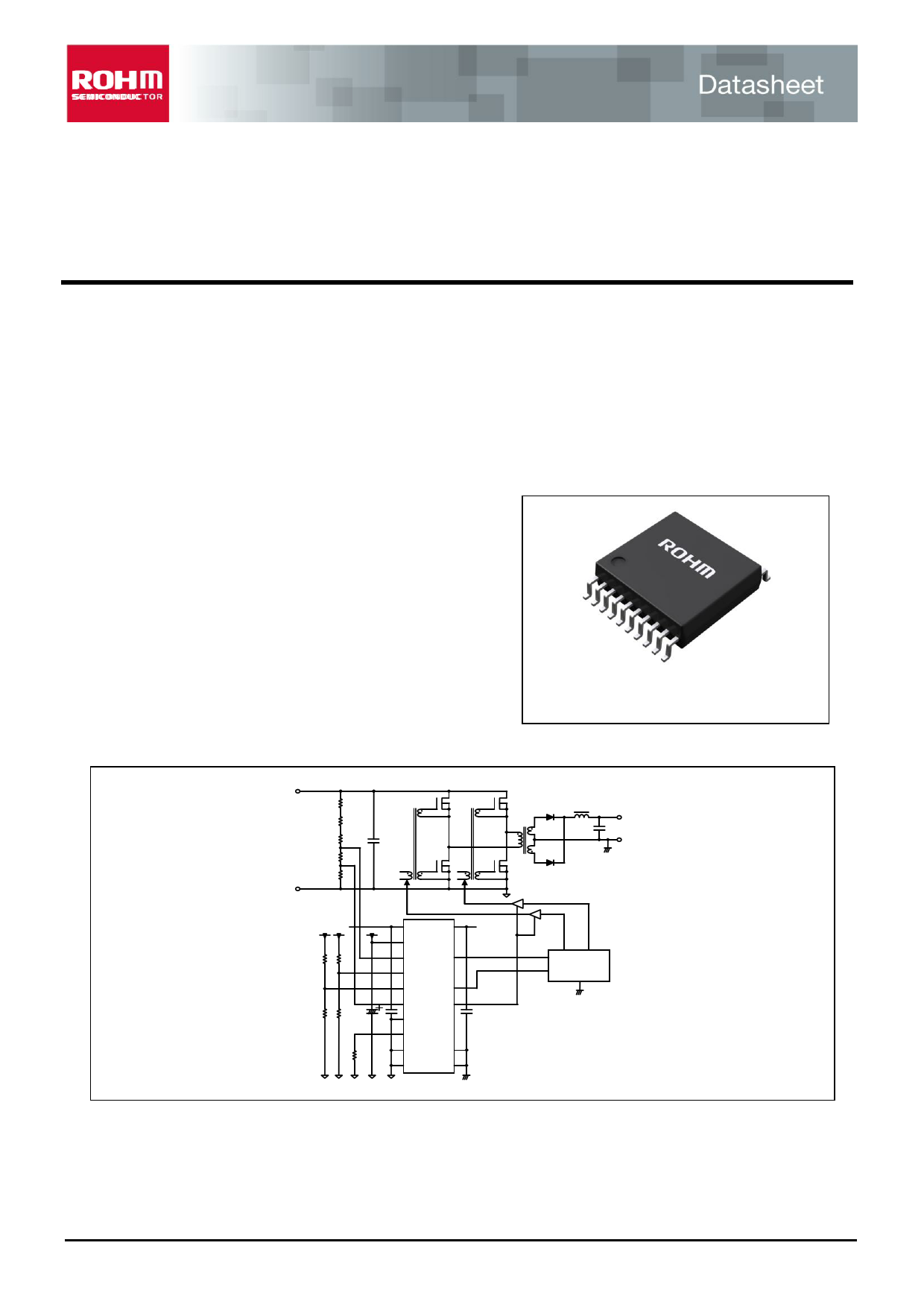
Typical Application Circuit
SSOP-B20W
6.50mm x 8.10mm x 2.01mm
VBIAS
VDD1 VDD2
REF NC
VH OUT
RFOV NC
RFLV SD1
VDTY SD2
VACT NC
RT NC
GND1 GND2
GND1 GND2
VBIAS
Controller
Figure 1. Example of a Typical Application Circuit of DC-DC Converter
○Product structure: Silicon integrated circuit ○This product has no designed protection against radioactive rays
www.rohm.com
© 2014 ROHM Co., Ltd. All rights reserved.
TSZ22111・14・001
1/30
TSZ02201-0727ABZ00010-1-2
10.Nov.2014 Rev.001
1 page 
BM67290FV-C
(2) Timing when VDD1 is ON first before VDD2
When VDD1 turns ON and reaches VthVDD1, REF turns ON. When REF reaches VthREF, CT turns ON.
When VDD2 turns ON, SD1=H, SD2=L and OUT=L initially..
When VDD2 reaches VthVDD2, DUTY will be immediately outputted to OUT pin at the next CLK pulse.
SD1 and SD2 behavior at CLK’s 2nd pulse is still the same with (1), SD1=L and SD2=Hi-Z at CLK’s 2nd pulse.
VTHVDD2
VDD2
0V
VTHVDD1H
VTHLVDD1L
VDD1
0V
VTHREFH
VTHREFH
REF
0V
VthOV,VthVACT
VthOV×VOVZ
VHVACT
VthHPWL
(CT)
VH
VDTY
VTHLV
VTHLV×VLVH
VTHLPWL
0V
H
(CLK)
L
VDD2
OUT
0V
H
(PRT1)
L
H
(PRT2)
L
VDD2
SD1
0V
Hi-Z
SD2
0V
Figure 4. VDD1 Start to VDD2 Start Timing Chart
www.rohm.com
© 2014 ROHM Co., Ltd. All rights reserved.
TSZ22111・15・001
5/30
TSZ02201-0727ABZ00010-1-2
10.Nov.2014 Rev.001
5 Page 
BM67290FV-C
(7) Under Voltage Detection (input low voltage protection)
When VH < VthLV×VLVH, input low voltage protection is activated. PRT2 immediately turns H.
At this time, OUT=”L”, SD1=”H”, and SD2=”L”.
When VH > VthLV, the protection circuit is deactivated and PRT2=L. OUT returns to normal operation, SD1 turns L
and SD2 turns Hi-Z at CLK’s 2nd pulse.
VthOV,VthVACT
VthOV×VOVZ
VHVACT
VthHPWL
( CT )
VH
VDTY
VthLV
VthLV×VLVH
VthLPWL
0V
H
( CLK )
L
VDD2
OUT
0
H
( PRT1 )
L
H
( PRT2 )
L
VDD2
SD1
0V
Hi-Z
SD2
0V
Figure 11. Protection Detection (input low voltage protection) Timing Chart
(8) UVLO Detection
This IC is equipped with UVLO circuits for VDD1 voltage, REF voltage and VDD2 voltage.
When any undervoltage is detected, OUT=L, SD1=H and SD2=L.
No
VDD1
UVLO
1L
2L
3L
4L
5H
6H
7H
8H
VDD2
UVLO
L
L
H
H
L
L
H
H
REF
UVLO
L
H
L
H
L
H
L
H
OUT
L
L
L
L
L
L
L
DUTY
OUTPUT
SD1 SD2
H
H
H
H
H
H
H
PROTECTION
OUTPUT
L
L
L
L
L
L
L
PROTECTION
OUTUT
H:Release L:Detection
Figure 12. Output Logic of the UVLO
www.rohm.com
© 2014 ROHM Co., Ltd. All rights reserved.
TSZ22111・15・001
11/30
TSZ02201-0727ABZ00010-1-2
10.Nov.2014 Rev.001
11 Page | ||
| Páginas | Total 30 Páginas | |
| PDF Descargar | [ Datasheet BM67290FV-C.PDF ] | |
Hoja de datos destacado
| Número de pieza | Descripción | Fabricantes |
| BM67290FV-C | High Voltage Detection IC | ROHM Semiconductor |
| Número de pieza | Descripción | Fabricantes |
| SLA6805M | High Voltage 3 phase Motor Driver IC. |
Sanken |
| SDC1742 | 12- and 14-Bit Hybrid Synchro / Resolver-to-Digital Converters. |
Analog Devices |
|
DataSheet.es es una pagina web que funciona como un repositorio de manuales o hoja de datos de muchos de los productos más populares, |
| DataSheet.es | 2020 | Privacy Policy | Contacto | Buscar |