|
|
|
PDF HCNR201 Data sheet ( Hoja de datos )
| Número de pieza | HCNR201 | |
| Descripción | High-Linearity Analog Optocouplers | |
| Fabricantes | AVAGO | |
| Logotipo | ||
Hay una vista previa y un enlace de descarga de HCNR201 (archivo pdf) en la parte inferior de esta página. Total 19 Páginas | ||
|
No Preview Available !
HCNR200 and HCNR201
High-Linearity Analog Optocouplers
Data Sheet
Lead (Pb) Free
RcoomHSpl6iafnutlly
RoHS 6 fully compliant options available;
-xxxE denotes a lead-free product
Description
The HCNR200/201 high-linearity analog optocoupler
consists of a high-performance AlGaAs LED that illumi‑
nates two closely matched photodiodes. The input pho‑
todiode can be used to monitor, and therefore stabilize,
the light output of the LED. As a result, the non-linearity
and drift characteristics of the LED can be virtually elimi‑
nated. The output photodiode produces a photocurrent
that is linearly related to the light output of the LED. The
close matching of the photo-diodes and advanced de‑
sign of the package ensure the high linearity and stable
gain characteristics of the optocoupler.
The HCNR200/201 can be used to isolate analog signals
in a wide variety of applications that require good stabil‑
ity, linearity, bandwidth and low cost. The HCNR200/201
is very flexible and, by approp riate design of the appli‑
cation circuit, is capable of operating in many different
modes, including: unipolar/bipolar, ac/dc and inverting/
non-inverting. The HCNR200/201 is an excellent solution
for many analog isolation problems.
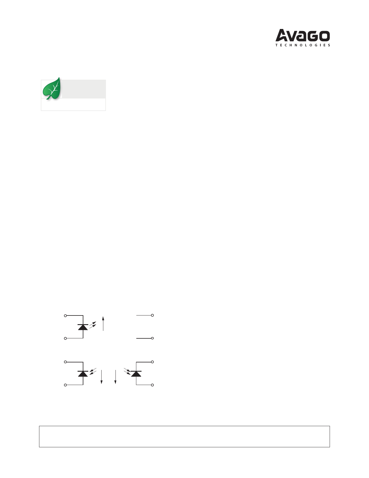
Schematic
1
LED CATHODE
-
VF
LED ANODE
+
2
IF
8
NC
NC
7
Features
• Low nonlinearity: 0.01%
• KH3C(NIPDR22/I0P0D1:)±tr1a5n%sfer gain
HCNR201: ±5%
• Low gain temperature coefficient: ‑65 ppm/°C
• Wide bandwidth – DC to >1 MHz
• Worldwide safety approval
– UL 1577 recognized (5 kV rms/1 min rating)
– CSA approved
– IEC/EN/DIN EN 60747-5-2 approved
VIORM = 1414 V peak (option #050)
• Surface mount option available (Option #300)
• 8-Pin DIP package - 0.400” spacing
• Allows flexible circuit design
Applications
• Low cost analog isolation
• Telecom: Modem, PBX
• Industrial process control:
Transducer isolator
Isolator for thermocouples 4 mA to 20 mA loop isola‑
tion
• SMPS feedback loop, SMPS feedforward
• Monitor motor supply voltage
• Medical
3
PD1 CATHODE
IPD1 I PD2
6
PD2 CATHODE
PD1 ANODE
4
PD2 ANODE
5
CAUTION: It is advised that normal static precautions be taken in handling and assembly
of this component to prevent damage and/or degradation which may be induced by ESD.
1 page 
Solder Reflow Temperature Profile
300
PREHEATING RATE 3 °C + 1 °C/–0.5 °C/SEC.
REFLOW HEATING RATE 2.5 °C ± 0.5 °C/SEC.
PEAK
TEMP.
245 °C
200
160
150
140
°°°CCC
100
2.5 C ± 0.5 °C/SEC.
3 °C + 1 °C/–0.5 °C
PREHEATING TIME
150 °C, 90 + 30 SEC.
30
SEC.
30
SEC.
ROOM
TEMPERATURE
00
50
NOTE: NON-HALIDE FLUX SHOULD BE USED.
100 150
TIME (SECONDS)
PEAK
TEMP.
240 °C
SOLDERING
TIME
200 °C
PEAK
TEMP.
230 °C
50 SEC.
200
TIGHT
TYPICAL
LOOSE
250
Recommended Pb-Free IR Profile
Tp
TL
217 °C
* 245 +0/-5 °C
RAMP-UP
3 °C/SEC. MAX.
Tsmax 150 - 200 °C
Tsmin
ts
PREHEAT
60 to 180 SEC.
tp
tL
25
t 25 °C to PEAK
TIME
TIME WITHIN 5 °C of ACTUAL PEAK TEMPERATURE
15 SEC.
RAMP-DOWN
6 °C/SEC. MAX.
60 to 150 SEC.
NOTES:
THE TIME FROM 25 °C to PEAK
TEMPERATURE = 8 MINUTES MAX.
Tsmax = 200 °C, Tsmin = 150 °C
NOTE: NON-HALIDE FLUX SHOULD BE USED.
Regulatory Information
The HCNR200/201 optocoupler features a 0.400” wide, eight pin DIP package. This package was specifically designed
to meet worldwide regulatory requirements. The HCNR200/201 has been approved by the following organizations:
UL
Recognized under UL 1577, Component Recognition
Program, FILE E55361
CSA
Approved under CSA Component Acceptance Notice
#5, File CA 88324
IEC/EN/DIN EN 60747-5-2
Approved under
IEC 60747-5-2:1997 + A1:2002
EN 60747-5-2:2001 + A1:2002
DIN EN 60747-5-2 (VDE 0884 Teil 2):2003-01
(Option 050 only)
5
5 Page 
1000
900
800
700
600
500
400
300
200
100
0
0
PS OUTPUT POWER – mV
IS INPUT CURRENT – mA
25 50 75 100 125 150 175
TS – CASE TEMPERATURE – °C
Figure 11. Thermal derating curve dependence of safety limiting value
with case temperature per IEC/EN/DIN EN 60747-5-2.
CNR200 fig 11
R1
VIN
IPD1
+
PD1 A1
-
LED
IF
R2
IPD2
-
PD2 A2
+
R1
VIN
PD1
A) BASIC TOPOLOGY
C1
-
A1
+
VCC
LED
R3
PD2
R2
C2
-
PD2 A2
+
Figure 12. Basic isolation amplifier.
B) PRACTICAL CIRCUIT
CNR200 fig 12
VCC
VIN
-
+
-
+
VOUT
VOUT
VOUT
A) POSITIVE INPUT
B) POSITIVE OUTPUT
VIN
-
+
C) NEGATIVE INPUT
Figure 13. Unipolar circuit topologies.
CNR200 fig 13
11
-
VOUT
+
D) NEGATIVE OUTPUT
11 Page | ||
| Páginas | Total 19 Páginas | |
| PDF Descargar | [ Datasheet HCNR201.PDF ] | |
Hoja de datos destacado
| Número de pieza | Descripción | Fabricantes |
| HCNR200 | High-Linearity Analog Optocouplers | Agilent(Hewlett-Packard) |
| HCNR200 | High-Linearity Analog Optocouplers | AVAGO |
| HCNR201 | High-Linearity Analog Optocouplers | Agilent(Hewlett-Packard) |
| HCNR201 | High-Linearity Analog Optocouplers | AVAGO |
| Número de pieza | Descripción | Fabricantes |
| SLA6805M | High Voltage 3 phase Motor Driver IC. |
Sanken |
| SDC1742 | 12- and 14-Bit Hybrid Synchro / Resolver-to-Digital Converters. |
Analog Devices |
|
DataSheet.es es una pagina web que funciona como un repositorio de manuales o hoja de datos de muchos de los productos más populares, |
| DataSheet.es | 2020 | Privacy Policy | Contacto | Buscar |