|
|
|
PDF DS18B20 Data sheet ( Hoja de datos )
| Número de pieza | DS18B20 | |
| Descripción | Programmable Resolution 1-Wire Digital Thermometer | |
| Fabricantes | Dallas Semiconductor | |
| Logotipo | ||
 1. - Temperature Sensor - Maxim Hay una vista previa y un enlace de descarga de DS18B20 (archivo pdf) en la parte inferior de esta página. Total 27 Páginas | ||
|
No Preview Available !
www.dalsemi.com
FEATURES
Unique 1-Wire interface requires only one
port pin for communication
Multidrop capability simplifies distributed
temperature sensing applications
Requires no external components
Can be powered from data line. Power supply
range is 3.0V to 5.5V
Zero standby power required
Measures temperatures from -55°C to
+125°C. Fahrenheit equivalent is -67°F to
+257°F
±0.5°C accuracy from -10°C to +85°C
Thermometer resolution is programmable
from 9 to 12 bits
Converts 12-bit temperature to digital word in
750 ms (max.)
User-definable, nonvolatile temperature alarm
settings
Alarm search command identifies and
addresses devices whose temperature is
outside of programmed limits (temperature
alarm condition)
Applications include thermostatic controls,
industrial systems, consumer products,
thermometers, or any thermally sensitive
system
PRELIMINARY
DS18B20
Programmable Resolution
1-Wire® Digital Thermometer
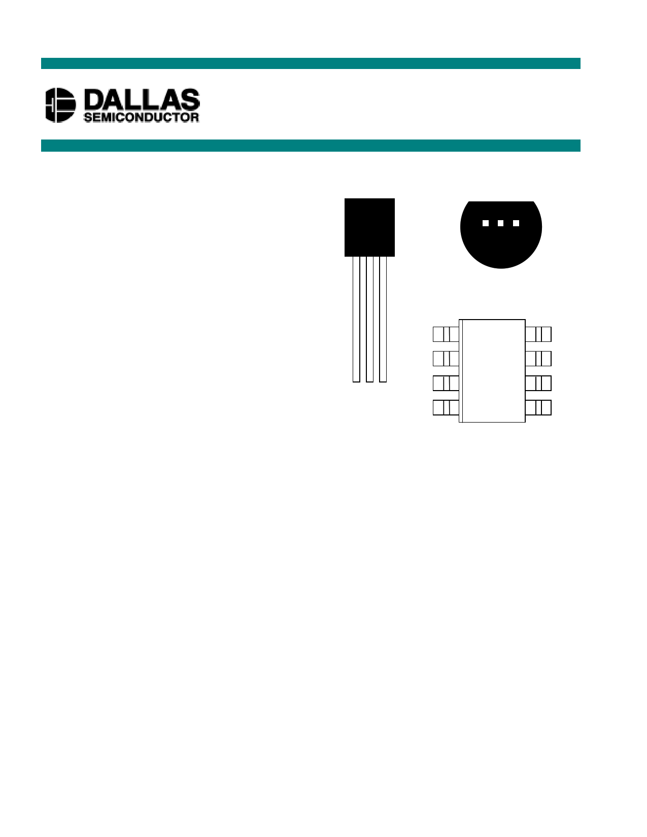
PIN ASSIGNMENT
DALLAS
DS1820
BOTTOM VIEW
123
123
DS18B20 To-92
Package
NC 1 8 NC
NC 2 7 NC
VDD 3 6 NC
DQ 4 5 GND
DS18B20Z
8-Pin SOIC (150 mil)
PIN DESCRIPTION
GND - Ground
DQ - Data In/Out
VDD - Power Supply Voltage
NC - No Connect
DESCRIPTION
The DS18B20 Digital Thermometer provides 9 to 12-bit (configurable) temperature readings which
indicate the temperature of the device.
Information is sent to/from the DS18B20 over a 1-Wire interface, so that only one wire (and ground)
needs to be connected from a central microprocessor to a DS18B20. Power for reading, writing, and
performing temperature conversions can be derived from the data line itself with no need for an external
power source.
Because each DS18B20 contains a unique silicon serial number, multiple DS18B20s can exist on the
same 1-Wire bus. This allows for placing temperature sensors in many different places. Applications
where this feature is useful include HVAC environmental controls, sensing temperatures inside buildings,
equipment or machinery, and process monitoring and control.
1 of 27
050400
1 page 
DS18B20
OPERATION - MEASURING TEMPERATURE
The core functionality of the DS18B20 is its direct-to-digital temperature sensor. The resolution of the
DS18B20 is configurable (9, 10, 11, or 12 bits), with 12-bit readings the factory default state. This
equates to a temperature resolution of 0.5°C, 0.25°C, 0.125°C, or 0.0625°C. Following the issuance of
the Convert T [44h] command, a temperature conversion is performed and the thermal data is stored in
the scratchpad memory in a 16-bit, sign-extended two’s complement format. The temperature
information can be retrieved over the 1-Wire interface by issuing a Read Scratchpad [BEh] command
once the conversion has been performed. The data is transferred over the 1-Wire bus, LSB first. The
MSB of the temperature register contains the “sign” (S) bit, denoting whether the temperature is positive
or negative.
Table 2 describes the exact relationship of output data to measured temperature. The table assumes 12-bit
resolution. If the DS18B20 is configured for a lower resolution, insignificant bits will contain zeros. For
Fahrenheit usage, a lookup table or conversion routine must be used.
Temperature/Data Relationships Table 2
23 22 21 20 2-1 2-2 2-3 2-4 LSB
MSb
(unit = °C)
LSb
S S S S S 26 25 24 MSB
TEMPERATURE DIGITAL OUTPUT
(Binary)
+125°C
+85°C
+25.0625°C
+10.125°C
+0.5°C
0°C
-0.5°C
-10.125°C
-25.0625°C
-55°C
0000 0111 1101 0000
0000 0101 0101 0000
0000 0001 1001 0001
0000 0000 1010 0010
0000 0000 0000 1000
0000 0000 0000 0000
1111 1111 1111 1000
1111 1111 0101 1110
1111 1110 0110 1111
1111 1100 1001 0000
DIGITAL
OUTPUT
(Hex)
07D0h
0550h*
0191h
00A2h
0008h
0000h
FFF8h
FF5Eh
FF6Fh
FC90h
*The power on reset register value is +85°C.
OPERATION - ALARM SIGNALING
After the DS18B20 has performed a temperature conversion, the temperature value is compared to the
trigger values stored in TH and TL. Since these registers are 8-bit only, bits 9-12 are ignored for
comparison. The most significant bit of TH or TL directly corresponds to the sign bit of the 16-bit
temperature register. If the result of a temperature measurement is higher than TH or lower than TL, an
alarm flag inside the device is set. This flag is updated with every temperature measurement. As long as
the alarm flag is set, the DS18B20 will respond to the alarm search command. This allows many
DS18B20s to be connected in parallel doing simultaneous temperature measurements. If somewhere the
temperature exceeds the limits, the alarming device(s) can be identified and read immediately without
having to read non-alarming devices.
5 of 27
5 Page 
DS18B20
INITIALIZATION
All transactions on the 1-Wire bus begin with an initialization sequence. The initialization sequence
consists of a reset pulse transmitted by the bus master followed by presence pulse(s) transmitted by the
slave(s).
The presence pulse lets the bus master know that the DS18B20 is on the bus and is ready to operate. For
more details, see the “1-Wire Signaling” section.
ROM FUNCTION COMMANDS
Once the bus master has detected a presence, it can issue one of the five ROM function commands. All
ROM function commands are 8 bits long. A list of these commands follows (refer to flowchart in
Figure 5):
Read ROM [33h]
This command allows the bus master to read the DS18B20’s 8-bit family code, unique 48-bit serial
number, and 8-bit CRC. This command can only be used if there is a single DS18B20 on the bus. If
more than one slave is present on the bus, a data collision will occur when all slaves try to transmit at the
same time (open drain will produce a wired AND result).
Match ROM [55h]
The match ROM command, followed by a 64-bit ROM sequence, allows the bus master to address a
specific DS18B20 on a multidrop bus. Only the DS18B20 that exactly matches the 64-bit ROM sequence
will respond to the following memory function command. All slaves that do not match the 64-bit ROM
sequence will wait for a reset pulse. This command can be used with a single or multiple devices on the
bus.
Skip ROM [CCh]
This command can save time in a single drop bus system by allowing the bus master to access the
memory functions without providing the 64-bit ROM code. If more than one slave is present on the bus
and a Read command is issued following the Skip ROM command, data collision will occur on the bus as
multiple slaves transmit simultaneously (open drain pulldowns will produce a wired AND result).
Search ROM [F0h]
When a system is initially brought up, the bus master might not know the number of devices on the
1-Wire bus or their 64-bit ROM codes. The search ROM command allows the bus master to use a
process of elimination to identify the 64-bit ROM codes of all slave devices on the bus.
Alarm Search [ECh]
The flowchart of this command is identical to the Search ROM command. However, the DS18B20 will
respond to this command only if an alarm condition has been encountered at the last temperature
measurement. An alarm condition is defined as a temperature higher than TH or lower than TL. The
alarm condition remains set as long as the DS18B20 is powered up, or until another temperature
measurement reveals a non-alarming value. For alarming, the trigger values stored in EEPROM are taken
into account. If an alarm condition exists and the TH or TL settings are changed, another temperature
conversion should be done to validate any alarm conditions.
11 of 27
11 Page | ||
| Páginas | Total 27 Páginas | |
| PDF Descargar | [ Datasheet DS18B20.PDF ] | |
Hoja de datos destacado
| Número de pieza | Descripción | Fabricantes |
| DS18B20 | Programmable Resolution 1-Wire Digital Thermometer | Maxim Integrated Products |
| DS18B20 | Programmable Resolution 1-Wire Digital Thermometer | Dallas Semiconductor |
| DS18B20-PAR | 1-Wire Parasite-Power Digital Thermometer | Maxim Integrated Products |
| DS18B20X | Flipchip 1-Wire Digital Thermometer | Dallas Semiconductor |
| Número de pieza | Descripción | Fabricantes |
| SLA6805M | High Voltage 3 phase Motor Driver IC. |
Sanken |
| SDC1742 | 12- and 14-Bit Hybrid Synchro / Resolver-to-Digital Converters. |
Analog Devices |
|
DataSheet.es es una pagina web que funciona como un repositorio de manuales o hoja de datos de muchos de los productos más populares, |
| DataSheet.es | 2020 | Privacy Policy | Contacto | Buscar |