|
|
|
PDF XCL210 Data sheet ( Hoja de datos )
| Número de pieza | XCL210 | |
| Descripción | 50mA/200mA Inductor Built-in Step-Down Converters | |
| Fabricantes | Torex Semiconductor | |
| Logotipo | ||
Hay una vista previa y un enlace de descarga de XCL210 (archivo pdf) en la parte inferior de esta página. Total 24 Páginas | ||
|
No Preview Available !
XCL210 Series
ETR28009-001a
50mA/200mA Inductor Built-in Step-Down “micro DC/DC” Converters
☆GreenOperationCompatible
■GENERAL DESCRIPTION
The XCL210 series is a synchronous step-down micro DC/DC converter which integrates an inductor and a control IC in one
tiny package (2.0mm×2.5mm, h=1.0mm). An internal coil simplifies the circuit and enables minimization of noise and other
operational trouble due to the circuit wiring. A wide operating voltage range of 2.0V to 6.0V enables support for applications
that require an internally fixed output voltage from 1.0V to 4.0V in increments of 0.05V.
During stand-by, all circuits are shutdown to reduce currentconsumption to as low as 0.1μA or less.
With the built-in UVLO (Under Voltage Lock Out) function, the internal P-channel MOS driver transistor is forced OFF when
input voltage becomes UVLO ditect Voltage or lower.
The XCL210 integrate CL discharge function which enables the electric charge at the output capacitor CL to be discharged via
the internal discharge switch located between the LX and VSS pins. When the devices enter stand-by mode, output voltage
quickly returns to the VSS level as a result of this function.
■APPLICATIONS
● Wearable Devices
● Smart meters
● Bluetooth units
● Energy Harvest devices
● Back up power supply circuits
● Portable game consoles
● Devices with 1 Lithium cell
■FEATURES
Input Voltage
: 2.0V~6.0V
Output Voltage
: 1.0V~4.0V (±2.0%, 0.05V step increments)
Control Methods
: PFM control
Output Current
: 200mA(XCL210A/XCL210C)
50mA(XCL210B/XCL210D)
Supply Current
: 0.5μA
High Efficiency
Function
: 93% (VIN=3.6V,VOUT=3.0V/100μA)
: UVLO
Short Circuit Protection
Capacitor
CL Discharge
: Low ESR Ceramic Capacitor
Operating Ambient Temperature : -40℃~+85℃
Packages
: CL-2025-02
Environmentally Friendly
: EU RoHS Compliant, Pb Free
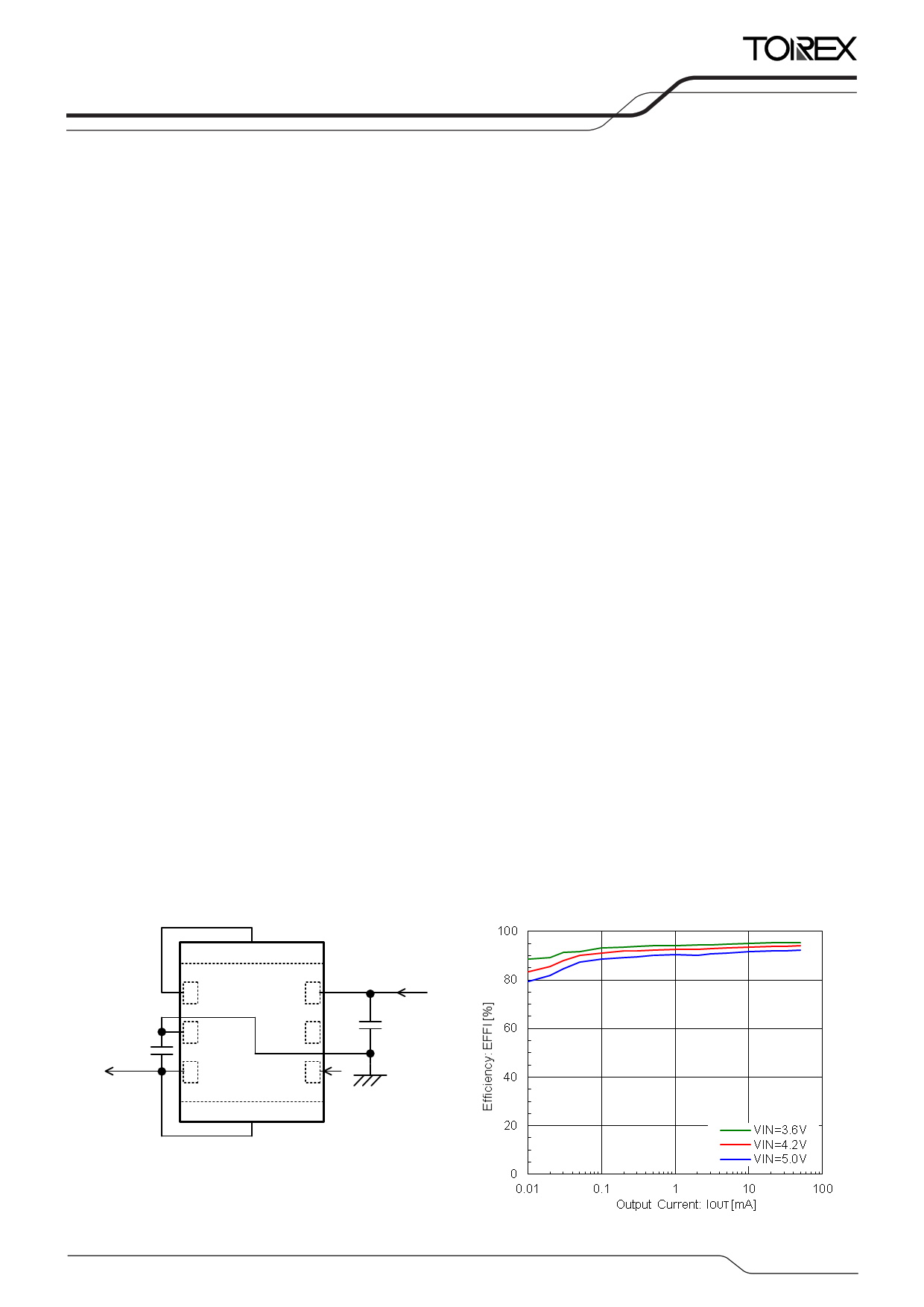
■TYPICAL APPLICATION CIRCUIT
■ TYPICAL PERFORMANCE
CHARACTERISTICS
XCL210B301GR-G(VOUT=3.0V)
50mA
CL
22μF
7
1 Lx
2 GND
VIN 6
NC 5
3 VOUT
8
CE 4
VIN
CIN
10μF
1/24
1 page 
XCL210
Series
■ELECTRICAL CHARACTERISTICS
●XCL210Axx1GR-G, without CL discharge function
PARAMETER
SYMBOL
CONDITIONS
MIN.
TYP.
Ta=25˚C
MAX. UNITS CIRCUIT
Input Voltage
VIN -
2.0 - 6.0 V
Output Voltage
VOUT(E) (*2)
Resistor connected with LX pin. Voltage which LX pin
changes “L” to “H” level while VOUT is decreasing.
E1
V
UVLO Release
Voltage
UVLO Hysteresis
Voltage
Supply Current
VUVLO(E)
VHYS(E)
Iq
VCE=VIN, VOUT=0V. Resistor connected with LX pin.
Voltage which LX pin changes “L” to “H” level while
VIN is increasing.
VCE=VIN, VOUT=0V. Resistor connected with LX pin.
VUVLO(E) - Voltage which LX pin changes “H” to “L”
level while VIN is decreasing.
VIN=VCE=VOUT(T)+0.5V (*1), VIN=2.0V, if VOUT(T)≦1.5V
(*1), VOUT=VOUT(T)+0.5V (*1), LX=Open.
1.65 1.80 1.95
V
0.11 0.15 0.24
V
E2 μA
Standby Current
LX SW “H” Leak
Current
ISTB
ILEAKH
VIN=5.0V, VCE=VOUT=0V, LX=Open.
VIN=5.0V, VCE=VOUT=0V, VLX=0V.
-
0.1 1.0
μA
-
0.1 1.0
μA
LX SW “L” Leak
Current
ILEAKL
VIN=5.0V, VCE=VOUT=0V, VLX=5.0V.
-
0.1 1.0
μA
PFM Switching
Current
IPFM
VIN=VCE=VOUT(T)+2.0V (*1), IOUT=10mA.
260 330 400
mA
Maximum
Duty Ratio (*3)
Efficiency (*4)
Efficiency (*4)
Efficiency (*4)
LX SW “Pch”
ON Resistance (*5)
MAXDTY
EFFI
EFFI
EFFI
RLXP
VIN=VOUT=VOUT(T)×0.95V(*1), VCE=1.2V
Resistor connected with LX pin.
VIN=VCE=5.0V, VOUT(T)=4.0V (*1), IOUT=30mA.
VIN=VCE=3.6V, VOUT(T)=3.3V (*1), IOUT=30mA.
VIN=VCE=3.6V, VOUT(T)=1.8V (*1), IOUT=30mA.
VIN=VCE=5.0V, VOUT=0V, ILX=100mA.
100 -
-
- 93 -
- 93 -
- 87 -
- 0.4 0.65
%
%
%
%
Ω
LX SW “Nch”
ON Resistance
RLXN
VIN=VCE=5.0V.
- 0.4 (*6) -
Ω
Output Voltage
Temperature
Characteristics
∆VOUT/
(VOUT・∆Topr)
-40℃≦Topr≦85℃.
- ±100
- ppm/℃
CE “High” Voltage
CE “Low” Voltage
VOUT=0V. Resistor connected with LX pin.
VCEH Voltage which LX pin changes “L” to “H” level while 1.2 - 6.0 V
VCE=0.2→1.5V.
VOUT=0V. Resistor connected with LX pin.
VCEL
Voltage which LX pin changes “H” to “L” level while
GND
-
0.3
V
VCE=1.5→0.2V.
CE “High” Current
ICEH VIN=VCE=5.0V, VOUT=0V, LX=Open.
-0.1 - 0.1 μA
CE “Low” Current
ICEL VIN=5.0V, VCE=VOUT=0V, LX=Open.
-0.1 - 0.1 μA
Short Protection
Threshold Voltage
Inductance Value
VSHORT
L
Resistor connected with LX pin.
Voltage which LX pin changes “H” to “L” level while
VOUT= VOUT(T)+0.1V→0V(*1).
Test Frequency=1MHz
0.4 0.5 0.6
- 8.0 -
V
μH
(Coil) Rated Current
IDC_L
∆T=+40℃
- 600 -
mA
Unless otherwise stated, VIN=VCE=5.0V
(*1) VOUT(T)=Nominal Output Voltage
(*2) VOUT(E)=Effective Output Voltage
The actual output voltage value VOUT(E) is the PFM comparator threshold voltage in the IC.
Therefore, the DC/DC circuit output voltage, including the peripheral components, is boosted by the ripple voltage average value.
Please refer to the characteristic example.
(*3) Not applicable to the products with VOUT(T) < 2.15V since it is out of operational volatge range.
(*4) EFFI=[{ (Output Voltage)×(Output Current)] / [(Input Voltage)×(Input Current)}]×100
(*5) LX SW “Pch” ON resistance = (VIN – VLX pin measurement voltage) / 100mA
(*6) Designed value
①
②
②
②
③
③
③
③
①
②
⑥
⑥
⑥
④
-
②
⑤
⑤
⑤
⑤
②
5/24
5 Page 
■TYPICAL APPLICATION CIRCUIT
XCL210
Series
VOUT CL
7
1 Lx
2 GND
VIN 6
NC 5
3 VOUT
8
CE 4
VIN
CIN
NOTE:
The integrated Inductor can be used only for this
DC/DC converter. Please do not use this inductor
for other reasons.
Manufacturer
Part Number
VALUE
LMK107BBJ106MALT
Taiyo Yuden
LMK212ABJ106MG
CIN C1608X5R1A106M
TDK
C2012X5R1A106M
10μF/10V
10μF/10V
10μF/10V
10μF/10V
LMK107BBJ226MA
Taiyo Yuden
LMK212BBJ226MG
CL
C1608X5R1A226M
TDK C2012X5R1A226M
22μF/10V
22μF/10V
22μF/10V
22μF/10V
* Take capacitance loss, withstand voltage, and other conditions into consideration when selecting components.
11/24
11 Page | ||
| Páginas | Total 24 Páginas | |
| PDF Descargar | [ Datasheet XCL210.PDF ] | |
Hoja de datos destacado
| Número de pieza | Descripción | Fabricantes |
| XCL210 | 50mA/200mA Inductor Built-in Step-Down Converters | Torex Semiconductor |
| XCL211 | 2.0A Inductor Built-in Step-Down micro DC/DC Converters | Torex |
| XCL212 | 2.0A Inductor Built-in Step-Down micro DC/DC Converters | Torex |
| XCL213 | 1.5A Inductor Built-in Step-Down Converters | Torex Semiconductor |
| Número de pieza | Descripción | Fabricantes |
| SLA6805M | High Voltage 3 phase Motor Driver IC. |
Sanken |
| SDC1742 | 12- and 14-Bit Hybrid Synchro / Resolver-to-Digital Converters. |
Analog Devices |
|
DataSheet.es es una pagina web que funciona como un repositorio de manuales o hoja de datos de muchos de los productos más populares, |
| DataSheet.es | 2020 | Privacy Policy | Contacto | Buscar |