|
|
|
PDF ACPL-K370 Data sheet ( Hoja de datos )
| Número de pieza | ACPL-K370 | |
| Descripción | Isolated Voltage/Current Detector | |
| Fabricantes | AVAGO | |
| Logotipo | ||
Hay una vista previa y un enlace de descarga de ACPL-K370 (archivo pdf) en la parte inferior de esta página. Total 13 Páginas | ||
|
No Preview Available !
ACPL-K370, ACPL-K376
Isolated Voltage/Current Detector
Data Sheet
Description
The ACPL-K370 and ACPL-K376 are voltage/current
threshold detection optocouplers. The ACPL-K376 is a low-
current version of the ACPL-K370. To obtain lower current
operation, the ACPL-K376 uses a high-efficiency AlGaAs
LED which has higher light output at lower drive currents.
Both devices have a threshold sensing input buffer IC
that allows threshold levels to be set by a single external
resistor over a wide range of input voltages.
The input buffer has several performance enhancing
features: hysteresis for extra noise immunity and
switching immunity, a diode bridge for easy use with AC
input signals, and internal clamping diodes to protect the
buffer and LED from over-voltage and over-current tran-
sients. Because threshold sensing is done prior to driving
the LED, variations in optical coupling from the LED to the
detector will not effect the threshold levels.
The ACPL-K370 input buffer IC has a nominal turn-on
threshold of 3.8 V(VTH+) and 2.77 mA (ITH+). The buffer
IC for the ACPL-K376 is designed for lower input current.
The nominal turn-on threshold for the ACPL-K376 is 3.8 V
(VTH+) and 1.32 mA (ITH+), which reduces power dissipa-
tion by 52%.
The high-gain output stage features an open-collector
output for both TTL compatible saturation voltages and
CMOS compatible breakdown voltages.
By combining many unique functions in a single package, the
ACPL-K370 and ACPL-K376 are ideal components for indus-
trial control computer input boards and other applications
where a predetermined input threshold level is needed.
Features
x ± 5% voltage detection accuracy
x Wide AC or DC detection range: up to 1140 Vpeak
x User configurable single/dual detection levels
x Built-in hysteresis improves noise immunity
x Very low threshold current: 1.32 mA (ACPL-K376)
x Logic compatible output
x Wide output supply voltage: 2 V to 18 V
x –40°C to +105°C operating temperature range
x SSO-8 package with 8 mm creepage and clearance
x Safety and regulatory approval:
– IEC/EN/DIN EN 60747-5-5: 1140 Vpeak working
insulation voltage
– UL 1577: 5000 Vrms/1minute double protection
rating
– CSA: Component Acceptance Notice #5
Applications
x Limit switch sensing
x Low voltage detector
x AC mains and DC-link voltage detection
x Relay contact monitor
x Relay coil voltage monitor
x Current sensing
x Microprocessor interfacing
x Telephone ring detection
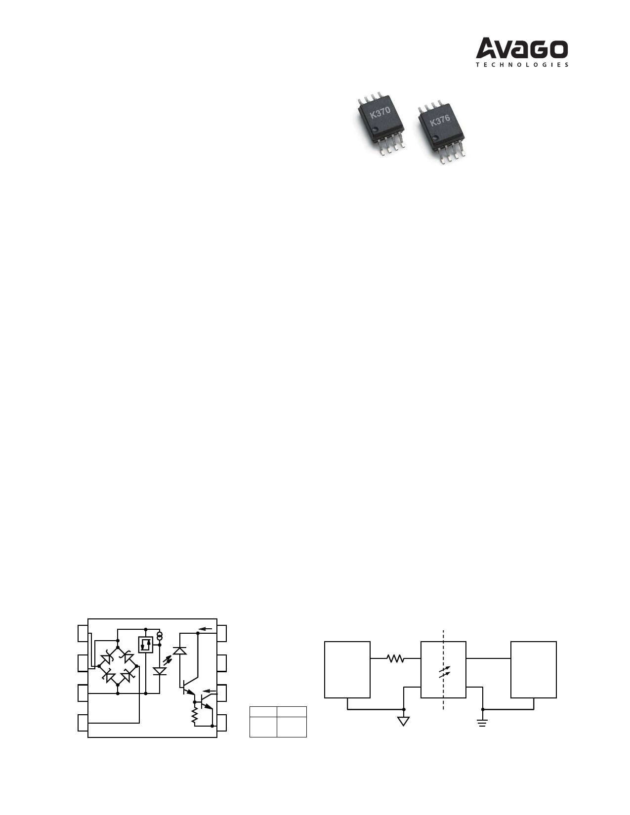
Functional Diagram
Connection Diagram
AC1 1
D1
DC+ 2
D3
DC 3
D2
D4
AC2 4
Figure 1. Functional Diagram
ICC
8 VCC
7 NC
IO 6 VO
TRUTH TABLE
(POSITIVE LOGIC)
5 GND
INPUT OUTPUT
HL
LH
AC/DC
POWER
ISOLATION BARRIER
RX
ACPL-K370
GND1 ACPL-K376
Figure 2. Connection Diagram
GND2
CONTROLLER
1 page 
Table 4. Absolute Maximum Ratings
Parameter
Symbol
Min
Max
Units Note
Storage Temperature
Operating Temperature
TS –55 125 °C
TA –40 105 °C
Input Current, Average
IIN
50 mA 1
Input Current, Surge
IIN
140 mA 1, 2
Input Current, Transient
IIN
500 mA 1, 2
Input Voltage (Pins 2-3)
VIN –0.5
V
Input Power Dissipation
PIN
200 mW 3
Total Package Power Dissipation
PT
269 mW 4
Output Power Dissipation
PO
163 mW 5
Output Current, Average
IO
30 mA 6
Supply Voltage (Pins 8-5)
VCC –0.5 20
V
Output Voltage (Pins 6-5)
Lead Solder Temperature
VO –0.5 20 V
260°C for 10 seconds, measured at 1.6 mm below seating plane.
Notes:
1. Current into or out of any single lead.
2. Surge input current duration is 3 ms at a 120 Hz pulse repetition rate. Transient input current duration is 10 μs at a 120 Hz pulse repetition rate. Note
that the maximum input power, PIN, must be observed.
3. Derate linearly above 105°C free-air temperature at a rate of 10 mW / °C. The maximum input power dissipation of 200 mW allows an input IC
junction temperature of 125°C at an ambient temperature of TA = 105°C. Excessive PIN and TJ may result in IC chip degradation.
4. Derate linearly above 105°C free-air temperature at a rate of 13.5 mW / °C.
5. Derate linearly above 105°C free-air temperature at a rate of 8.2 mW / °C. A maximum output power dissipation of 163 mW allows an output IC
junction temperature of 125°C at an ambient temperature of TA = 105°C.
6. Derate linearly above 105°C free-air temperature at a rate of 1.5 mA / °C.
Table 5. Recommended Operating Conditions
Parameter
Symbol
Min
Max
Units Note
Supply Voltage
VCC 2
18 V
Operating Temperature
Operating Frequency, VCC = 5 V
TA –40 105 °C
f 0 9 kHz 1
Operating Frequency, VCC = 3.3 V
f
0 5 kHz 1
Notes:
1. Maximum operating frequency is defined when the output waveform at pin 6 obtains only 90% of VCC with RL = 4.7 k:, CL = 30 pF using a 5 V
square wave input signal.
5
5 Page 
40
35 RL = 4.7k:,
CL = 30pF,
30 VCC = 4.5V
25
20
ACPL-K370
tPLH
40
35 RL = 4.7k:,
CL = 30pF,
30 VCC = 4.5V
25
20
15 15
10 10
5 tPHL 5
0
-60 -40 -20
0 20 40 60
TA - TEMPERATURE - °C
(a)
80 100 120
0
-60 -40 -20
Figure 10. Typical propagation delay vs. temperature for (a) ACPL-K370 and (b) ACPL-K376.
ACPL-K376
tPLH
tPHL
0 20 40 60
TA - TEMPERATURE - °C
(b)
80 100 120
ACPL-K370
80 900
70 RL = 4.7k:,
CL = 30pF,
60 VCC = 4.5V
50
800
tR 700
600
80
70 RL = 4.7k:,
CL = 30pF,
60 VCC = 4.5V
50
ACPL-K376
tR
1000
900
800
700
40
500 40
600
30
tF 400
30
tF
500
20
300 20
400
10
200 10
300
0-60 -40 -20 0 20 40 60 80 100 120100
TA - TEMPERATURE - °C
(a)
0
-60 -40 -20
200
0 20 40 60 80 100 120
TA - TEMPERATURE - °C
(b)
Figure 11. Typical rise, fall times vs. temperature for (a) ACPL-K370,and (b) ACPL-K376.
ACPL-K370
300
250 V+(AC) V–(AC)
V+(DC)
V–(DC)
200
ACPL-K376
300
250 V+(AC)
V–(AC)
V+(DC)
V–(DC)
200
150
100
DC: VTH+ = 3.8V, VTH– = 2.59V;
AC: VTH+ = 5V, VTH– = 3.8V;
ITH+ = 2.77mA, ITH– = 1.44mA
50 (AC VOLTAGE IS
INSTANTANEOUS VALUE)
0 0 40 80 120 160 200 240
RX - EXTERNAL SERIES RESISTOR - k:
(a)
150
100
50
00
Figure 12. Typical external threshold characteristics, V± vs. RX for (a) ACPL-K370 and (b) ACPL-K376.
DC: VTH+ = 3.8V, VTH– = 2.59V;
AC: VTH+ = 5V, VTH– = 3.8V;
ITH+ = 1.32mA, ITH– = 0.68mA
(AC VOLTAGE IS
INSTANTANEOUS VALUE)
100 200 300 400
RX - EXTERNAL SERIES RESISTOR - k:
(b)
500
11
11 Page | ||
| Páginas | Total 13 Páginas | |
| PDF Descargar | [ Datasheet ACPL-K370.PDF ] | |
Hoja de datos destacado
| Número de pieza | Descripción | Fabricantes |
| ACPL-K370 | Isolated Voltage/Current Detector | AVAGO |
| ACPL-K376 | Isolated Voltage/Current Detector | AVAGO |
| Número de pieza | Descripción | Fabricantes |
| SLA6805M | High Voltage 3 phase Motor Driver IC. |
Sanken |
| SDC1742 | 12- and 14-Bit Hybrid Synchro / Resolver-to-Digital Converters. |
Analog Devices |
|
DataSheet.es es una pagina web que funciona como un repositorio de manuales o hoja de datos de muchos de los productos más populares, |
| DataSheet.es | 2020 | Privacy Policy | Contacto | Buscar |